Digital Floor Plans
Enabling Better Facility Management
Interest in surveying the inside of buildings is on the rise as computer-run digital floor plans are increasingly adopted for facility management. This is causing architects and surveyors alike to move away from blueprints towards Computer Aided Design (CAD). The authors describe a successful test for rapid creation of floor plans of a newly constructed building using simple measuring devices and a recently developed software tool.
The test site was on the campus of Nyiregyhazi Foiskola, a university in eastern Hungary which maintains its buildings and other facilities using Computer Aided Facility Management (CAFM) based on the CMMS (Computer Maintenance Management System) ArchiFM, from VintoCON. In Hungary, architects and CAD services companies, including Devi cad-studio, are replacing paper floor plans with 2D (floor plans) and 3D Building Information Models (BIM). Devi has used diverse graphical and facility management software for a variety of projects, and to test the feasibility of OrthoGraph, a software tool released in 2007 and fully fitted for integration with ArchiFM, a newly constructed building on the Nyiregyhazi Foiskola campus was selected for survey.
Devices and Site
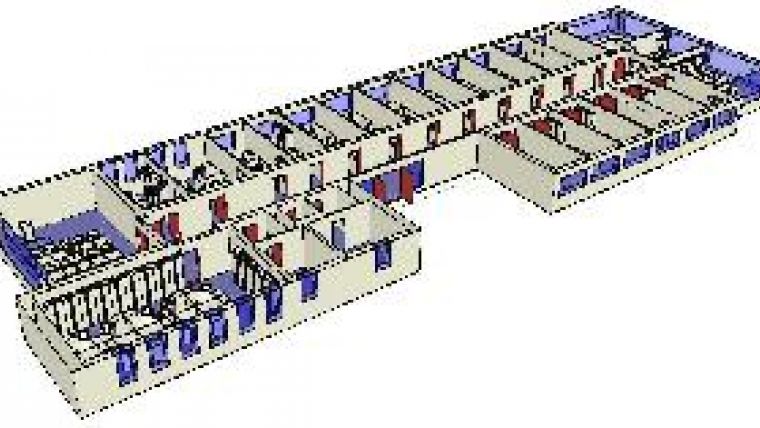
The creation of digital floor plans and 3D BIM requires a complete and up-to-date inventory of building structures, heating systems, power and communication cables, and many more objects fixed to the concrete or other construction materials. To carry out the survey at the new building, a PDA (Hewlett Packard iPaq 214 Enterprise) was equipped with OrthoGraph; a package specially developed for surveying buildings and constructions and creating floor plans using handhelds. In order to collect geometric data, distance measurements were conducted using a Leica Disto A6, a laser distance meter specially developed for tight linking with PDAs on which ‘Windows mobile’ has been installed. Attribute information of objects was collected using a barcode scanner. Distance meter and scanner were both wirelessly connected to the handhelds by Bluetooth, enabling instant data transfer. The office building, covering a total area of approximately 800m2, consists of thirty rooms, each about 15m2 in size, and one long straight hallway of 125m2 (Figure 1). At one end of the building there is a meeting room, a classroom and two washrooms, and at the other end two larger offices and the reception desk. Around 400 objects are present in the building, on which barcodes were pasted. When scanning a barcode with a barcode scanner, material, location and other properties of meeting-room chairs, classroom projectors and many other types of object are shown on the handheld, which information is necessary for inventory purposes and project management needs.
Measure and Check
The dimensions of the rooms, including their windows and doors, were determined by measuring around ten distances per room: two height measurements (floor to ceiling); two room lengths; two room widths; width and height of door, and width and height of window. The dimensions of the hallway could be captured in six distance measurements, but the width and height of all doors leading to rooms and outdoors had also to be measured. Since all hallway doors have the same dimensions, the height and width values revealed from measuring the first door were attributed to all other doors, the first measurements thus taken as standard. The outside dimensions of the building were also measured to determine the thickness of inner and outer walls. The software features a support tool indicating which measurements have to be taken to fully cover the space. As input data this support tool requires a plan of the building previously sketched by the surveyor. The tool is valuable because it significantly reduces the chance that the surveyor will overlook crucial elements of rooms and halls. In addition, it forces the surveyor to take redundant measurements, which facilitates checking and removal of erroneous measurements (Figure 2).
The integration with ArchiFM enables uploading of the data to the university’s CAFM database. After opening the file in ArchiCAD, a 3D model can be created. Planimetric plans of all the rooms in the building and facilities present there, such as heating, ventilation, and air conditioning, can also be displayed. This so-called ‘room book’ thus displays on separate pages detailed information about each room or other parts of the building (Figure 3).
Concluding Remarks
The capability to store onsite information at the PDAs proved particularly helpful. Surveyors benefited from both the digital sketches and the database providing an inventory of objects present in the building. The developed digital workflow revealed itself to be more efficient than dealing with paper and pencil. Instead of three surveyors working on site for six weeks plus two weeks offsite data processing, the entire job of data collection and processing could be finished in two weeks, including initial training, while processing of the data proceeded smoothly.

Value staying current with geomatics?
Stay on the map with our expertly curated newsletters.
We provide educational insights, industry updates, and inspiring stories to help you learn, grow, and reach your full potential in your field. Don't miss out - subscribe today and ensure you're always informed, educated, and inspired.
Choose your newsletter(s)


