Terrestrial Laser Scanning
How Terrestrial Laser Scanning Works and What It Does
Terrestrial laser scanners are contact-free measuring devices which can collect dense point-clouds of objects. After processing each point is assigned with X, Y, Z coordinates; colour and reflectance value. The relative precision, that is the ratio between absolute precision and measurement range, is better than 10-4. This technology is becoming increasingly important for surveying applications. The authors provide an overview of how the technology works, illustrated by examples from their own research activities.
Lasers emit electromagnetic radiation, which is coherent and monochromatic. The emitted beams are highly directional, contain a lot of energy, bridge hundreds of metres and are reflected from the surfaces of objects. These are very beneficial properties, and laser is thus increasingly used as the principle component in distance measurement devices able to create 3D models of objects of a wide range of sizes and shapes.
Laser Sensor Reflectance
The return energy caught by the receiver part of the laser sensor depends on the reflective characteristics of the surface of an object mathematically expressed as the reflection coefficient: that is the ratio between reflected energy and incident energy. The reflection coefficient of smooth and bright surfaces lies between 70% and 100%, but falls to 20% when surfaces become more rough and dark. A measurement is only usable if the return energy lies above a certain threshold. The precision of a measurement depends on distance between laser sensor and object, beam divergence, shape and reflectivity of the object, and environmental conditions.
Principles of Terrestrial Laser Scanning
Measuring with laser sensors may be based on four principles:
time-of-flight: pulses are emitted and their travel time to and back from the object is measured, multiplied by the speed of light and divided by two phase difference: waves are modulated in width or frequency; width modulation is sensitive to sharp discontinuities in shape or reflectance of the object, while frequency modulation provides reliable measurements even when return energy is low optical triangulation, for short-range applications and small objects interferometry, which offers very high precision and is used in indoor industrial metrology.
Today, using time-of-flight technology, pulses can be digitised and matching between emitted and return energy thus done computationally. This avoids the setting of a minimum threshold, reduces the time of measuring at individual points, and eliminates other limitations. The Riegl VZ-400, now available as VZ-1000, is the first such terrestrial laser scanner that digitises signals. The shape of the signal reconstructed from its digitised version provides a clue as to the reflection characteristics of the surface of the object, hence allowing determination of its morphology.
Laser Scanners
Here presented are the scanners which we use in our research. Laser-radar MV224 and MV260 from Belgian Metris are based on frequency modulation and can acquire up to 1,000 points per second indoor or outdoors, with a range up to 60m. They operate under any light conditions and the threshold of the return energy is just 1% of that emitted, so they can capture very dark or very light objects such as statues, aeroplanes and ships. The relative precision is 10-5, that is 0.1mm at 10m and 0.240mm at 24m. The field of view is 360° (azimuth) x 120° (zenith) and the high precision and 1% threshold for return energy are favourable qualities for monitoring deformation, factures and construction displacement.
Zoller&Fröhlich Imager 5006i and 5006h (Figure 1a), also offered by Leica as HDS6100 and 6200 (Figure 1b), has a maximum range up to 80m and can acquire 500,000 to 1,000,000 points per second, allowing its use as the laser-sensor component of mobile-mapping systems. The relative precision is better than 10-4, that is a few millimetres at 50m. The threshold of the return energy is 10% of the emitted energy. The time needed to capture the scene within the field of view of 360° x 310° is twenty to forty minutes, even when the scanning interval is extremely small. For photo-texturing purposes, a motorised camera (M-Cam) can be mounted on the scanner (Figure 1a), or a reflex camera supported by a bracket (Figure 1c) can be used for manual image collection. The recent Imager 5010 has a maximum range up to 190m and field of view of 360° x 320°.
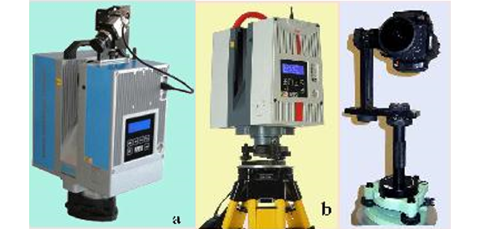
Leica Scan Station C10, offering both panoramic scanning and the features of a motorised total-station, can acquire 50,000 points per second and is provided with an internal camera.
Survey Set-up
When planning a laser-scanning survey the subsequent positions of the scanner must be carefully chosen such that sufficient overlap of the point-clouds is ensured. Also important are good visibility of the objects in the scene and absence of pedestrians, vehicles, animals and other temporary obstructions, as well as overhang, trees and other occluding objects: these are the main cause of data voids. The scanning interval in horizontal and vertical direction should be equivalent and small enough to allow for capturing all desired details. The scanning interval is determined by setting an angular value. How much this interval is in centimetres depends on the distance and orientation of the laser sensor with respect to the object. There is a strong relationship between level of detail (or scale), scanning interval, precision and object size (Table 1, below). In the table, scanning interval and precision are set equal because according to heritage specifications scanning interval should be equal to or less than precision.
|
Scale |
Scanning Interval (mm) |
Precision (mm) |
Max. Object Size (M) |
|
1:10 |
2 |
2 |
5x5 |
|
1:20 |
4 |
4 |
10x10 |
|
1:50 |
15 |
15 |
20x30 |
|
1:100 |
25 |
25 |
40x60 |
Table 1: scanning interval and precision
When photo-texturing of the final 3D model is required, a camera should capture the scene along with the laser scanner. A built-in camera allows automatic texturing of the 3D model, since the orientation parameters with respect to the scanner are precisely known. However, when the camera is external each image has to be linked to the corresponding point-cloud using manually selected tie points. Proper photo-texturing requires avoidance of over- or under-expositions and the occurrence of shadows. The radiometric characteristics of the images should also be carefully balanced and their spatial resolution better than the scanning interval of the laser scanner.
Terrestrial Laser Scanning Software
Software is essential for controlling the scanner during surveying and to process the raw data into measurable point-clouds and 3D models. The manufacturer of the laser scanner usually provides the control software that steers the movement of the scanner, visualises object points during scanning in 2D or 3D, and carries out onsite data cleaning. Processing of raw data into measurable 3D models, the most difficult and major task, is done in the office with sophisticated application software, which is rather expensive.
Software is also necessary to join the point-clouds gathered at the sequence of scan positions into one model, and to geo-reference the model within a desired coordinate system. When object surfaces are rich in detail, the joining of point-clouds can best be done by feature matching rather than using targets as tie point, since these may become invisible from certain viewpoints. Feature matching allows the use of a dense set of well distributed natural tie points and so results in improved quality of the final 3D model. Furthermore, the many targets required for creating richly detailed 3D models may disrupt and spoil the appearance of a final textured model.
Examples of Terrestrial Laser Scanning
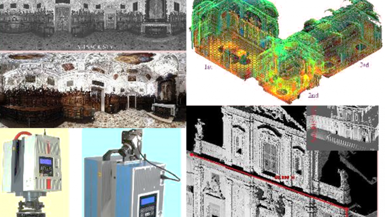
We recently surveyed the interiors of the three Sacristies of St Martino Church in Alzano Lombardo, close to Bergamo, Northern Italy, famous for their baroque frescos, stuccos and inlays. We used a Leica HDS 6100 and Zoller&Fröhlich 5600i, equipped with an M-cam. From the multitude of scans we created one measurable 3D point model (Figure 2). Figure 3 (top) shows the model of the second Sacristy in greater detail; reflectance values are shown in black/white. On this model we superimposed colour images (Figure 3, bottom). Next we transformed the 3D point-model into a 2D model, which is a better representation for 3D reconstructed details, 2-D line-plotting, creating profiles, sections and orthophotos (Figures 4).
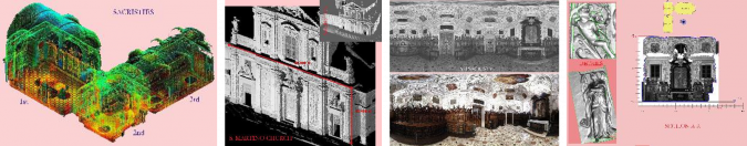
The scanning technology makes the borders of pillars and statues and other discontinuities appear rather jagged, obstructing correct and exact outlining of object geometry. To improve quality, line-plotting from the point-cloud can be supported by edge-detection techniques applied to the images. Images are thus not only a source of photo-texture, but also valuable in support of accurate and reliable plotting.
Acknowledgements
Thanks are due to the team from Geo-technology Lab, Leica Geosystems and 3DTarget.
Further Reading
- Colombo L., Marana B., 2010, Building Reconstruction and Texturing, Geoinformatics, No.2
- Colombo L., Marana B., 2009. Photo-textured Building Models, GEOconnexion, No. 2
- Doneus M., Pfennigbauer M., Studnicka N., Ullrich A., 2009, Terrestrial Waveform Laser Scanning for
- Documentation of Cultural Heritage - Proceedings of CIPA - Kyoto (Japan)
- Lemmens, M., Terrestrial Laser Scanners, 2010, GIM International, 24,8

Value staying current with geomatics?
Stay on the map with our expertly curated newsletters.
We provide educational insights, industry updates, and inspiring stories to help you learn, grow, and reach your full potential in your field. Don't miss out - subscribe today and ensure you're always informed, educated, and inspired.
Choose your newsletter(s)


