
There is a general acknowledgement in the scanning and mapping industry that, compared to terrestrial laser scanners (TLS), mobile mapping systems significantly increase scanning speed and point cloud coverage. This is especially true for building interiors and equipment. This results in reduced time on site, which in turn lowers the cost of scanning for the service provider.
So why isn’t every scanning service provider switching from a TLS to a mobile system? The answer is that there is still a lot of hesitation concerning the data quality that mobile mapping systems can achieve, as well as uncertainty about which of the established scan-to-CAD/BIM workflows run smoothly with data from mobile systems. As a result, many laser scanning professionals and surveyors tend to ask the following question:
“I see the advantages of mobile mapping for data acquisition, but how do I make sure that I am not losing time downstream during the creation of deliverables such as CAD drawings or BIM models?”
2D Drafting of As-built Conditions in CAD
Globally, most as-built documentation is still commissioned in 2D. The most common way of creating 2D floor plans and elevations of existing buildings from point clouds is to use horizontal and vertical slices with a thickness of a few decimetres as blueprints. The best practice for horizontal sections is to slice the registered point cloud twice: right underneath the ceiling to minimize furniture in the point cloud, and at a height of 1.20-1.50m, to obtain a correct representation of openings such as doors and windows. This usually happens in point cloud editing software. The point cloud sections are then exported to a suitable CAD software of choice, where the outlines of building components and sometimes equipment, furniture and other assets are traced in a manual drafting process.
Using NavVis point cloud data, detailed floor plans and elevations can typically be drafted at a scale of 1:100 or 1:50. Aside from this, the highly reliable accuracy, low point cloud noise and high resolution of fine details are key for the efficient creation of deliverables that meet the project requirements.
Additionally, NavVis IndoorViewer enables seamless navigation through detailed panoramic imagery captured on site during the mapping. These panoramic images help to resolve any ambiguity in the point cloud representation (e.g. “Is this a piece of furniture or a building element?”) in a fast and reliable manner.
3D Modelling of As-built Conditions in BIM
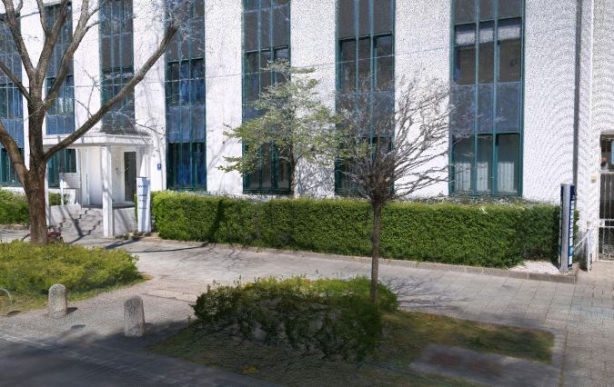
Although 2D representations for as-built documentation are still widely used, the demand for BIM is growing fast. The number of governmental mandates for public projects is increasing and large corporate owners are requesting BIM deliverables for private projects. The creation of a BIM model from a registered point cloud usually starts with an initial ‘cleaning’ of the data, removing points that are irrelevant such as plants or facades of neighbouring buildings. The next step involves importing the data into a BIM modelling tool of your choice.
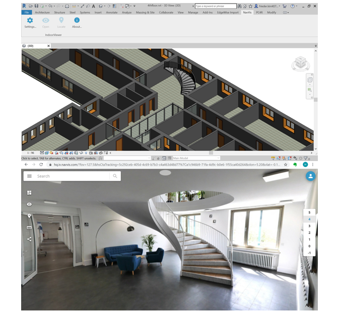
In this example, we use Autodesk Revit: after the import is completed successfully you can begin the modelling process by structuring the point cloud according to the building levels. This gives you the advantage of being able to model your building floor by floor, displaying only the points that are relevant. In doing this, building components such as walls, columns or openings can be identified and modelled easily in a manual process.
Based on NavVis data, BIM models with a Level of Development (LOD) 300 are the typical deliverables.
In addition to the highly reliable accuracy, the low point cloud noise, realistic colouring and high resolution of fine details are essential for an efficient modelling process.
A great example of this is the survey project of a historic metro station in Vienna by Vermessung Schubert ZT. What is more, the NavVis IndoorViewer add-in for Autodesk Revit enables users to directly jump to the relevant panoramic images, by clicking on the desired location in the Revit model. The panoramic imagery displaying the real-world conditions of the site helps users to better understand the on-site surroundings and model fine details that are often hard to identify using only the point cloud, such as switches, plugs or detailed structural joints.
Visualization and Simulation using Point Clouds
In process industries such as the chemical or oil and gas industries, and in offshore projects in particular, point clouds are often used to directly represent the as-is state of a facility in a 3D model, without remodelling existing conditions. In such cases, the point cloud is removed where equipment should be de-installed, and new equipment is modelled with CAD/BIM elements. This approach speeds up planning because the amount of manual remodelling work is substantially reduced. Such ‘hybrid’ modelling approaches allow for visual interference checks and clash detection between the point cloud and the model of new equipment for production engineering and the planning of equipment removal, transportation and installation.
In recent years, this approach has also gained popularity in discrete manufacturing, such as the automotive industry, for example for layout planning, assembly planning and process simulation. Furthermore, in non-industrial buildings with complex equipment and processes, such as hospitals, this approach is currently being used for refurbishment and reuse projects.
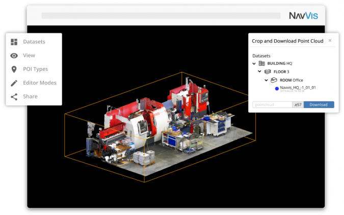
NavVis point cloud data is particularly well suited for this application. This is because large industrial spaces can be quickly and accurately scanned using NavVis technology. The resulting point cloud with low noise and highly realistic texture and colouring makes the data ideally suited for visualization of production equipment such as charge carriers and machines. In situations such as these, the download point cloud feature in NavVis IndoorViewer is perfectly suited: point cloud sections, such as a specific piece of equipment, can be selected and downloaded directly from the browser window. Further integrations with production planning software such as 3DExperience Platform from Dassault Delmia form the basis of more advanced applications such as process and material flow simulations.
Vectorization for Speeding Up the 2D Drafting Process
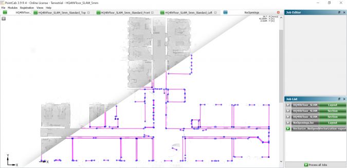
The manual tracing and drafting process for creating 2D CAD deliverables, as described above, is time consuming. Today, commercially available software packages such as PointCab offer powerful vectorization functions, which speed up the drafting process significantly. In PointCab, the user generates a horizontal or vertical section through the point cloud. This section can then be used to apply the vectorization function. As a result, a set of best-fit 2D lines are generated. These lines are not yet a complete plan but are a great start for the remaining 2D drafting steps, which include cleaning and completing the outlines of walls and rooms, as well as adding hatches and symbols for doors and windows. This is usually done in a CAD software package. Additionally, the vectorization algorithms help to reduce manual drafting inaccuracies to a minimum.
NavVis point cloud data is well suited for this workflow due to the comparably high accuracy standards and the high resolution of fine details in the point cloud. Furthermore, the live feedback displayed during mapping helps the operator to achieve maximum point cloud coverage. This reduces blind spots or gaps in the point cloud, which is crucial for a vectorization result that minimizes manual rework. In the vectorization example below, we have chosen a section height above the door openings, to ensure room outlines with maximum completeness. This result drastically reduces the manual drafting effort.
Object Extraction for Efficiency in 3D Modelling
When as-built BIM documentation is required, manual modelling and tracing processes based on point clouds are typically used. However, depending on the required LOD, these manual processes can be very time consuming and thus expensive. While a fully automatic one-click scan-to-BIM process still seems to be a futuristic vision, impressive steps have recently been made in exactly this direction.
In this document, we will touch upon two specific use cases, where automatic or semi-automatic object extraction is currently being used, with EdgeWise software tools from ClearEdge3D (also available as a plug-in for Autodesk Revit). The first application is the automatic generation of building components such as levels, walls and ceilings from point clouds. This is a one-click approach, and the results are impressive. Naturally, this does not result in a complete BIM model because doors and windows are still missing and some elements need to be cleaned up (e.g. door leaves are often represented as walls). However, according to one of ClearEdge3D’s clients, this results in a modelling process that is up to ten times faster.
Another prominent EdgeWise application is the semi-automatic extraction of pipes and structural elements from the point cloud. To do this, the user selects a region of the point cloud and the software automatically creates a best-fit pipe geometry. Further tools allow the creation of joints and T-connections between pipe elements. This substantially speeds up the manual modelling process and thus reduces cost.
ClearEdge3D has noticed the major benefits of mobile mapping systems in terms of data acquisition efficiency. This means that the above workflow is not only possible with point cloud data from TLS (‘structured data’), but also with data from mobile mapping systems (‘unstructured data’).
NavVis point cloud data is particularly well suited to this, due to the comparably high accuracy standards and the low noise in the point cloud. In recent internal reliability tests conducted by NavVis, pipes with diameters of 105mm, 75mm and 60mm were reliably detected from scanning distances of both 2 and 5 metres. Also, the automatic creation of walls and levels delivered highly satisfactory results in the tests based on NavVis data.
Review of NavVis Data Quality
Relative and absolute accuracy: All SLAM-based mobile mapping systems face challenges with drift, especially when the project does not allow for ‘loop closures’. NavVis has developed proprietary SLAM algorithms that reduce drift to a minimum. Furthermore, both NavVis mapping devices – NavVis M6 and NavVis VLX – enable the use of control points (measured targets) to validate relative (local) and absolute (global) accuracy. Finally, the NavVis post-processing software allows optimization of the absolute accuracy based on measured control points. For a comprehensive discussion on accuracy in the context of mobile mapping, refer to the Indoor Mobile Mapping Accuracy Handbook.
Point cloud noise: Data from mobile mapping systems usually has a higher noise level compared to data from a TLS. For popular handheld systems, this results in a ‘line’ of up to 3cm ‘thickness’, representing flat, vertical surfaces such as walls in horizontal sections. The filtering algorithms in NavVis post-processing software reduce the noise to a minimum, resulting in sharp, straight lines in sections. These results are far more comparable to the data of TLS than to other mobile mapping devices on the market.
Resolution of fine details: The unique and proprietary filtering algorithms of NavVis post-processing software ensure the preservation of fine geometric details during the point cloud filtering process, such as the profiles framing the opening of the elevator door above. This ensures that floor plans with a scale up to 1:50 can be created based on the data.
Colouring of point clouds: While other mobile mapping devices create point clouds with either dull or no colour, NavVis creates point clouds with highly realistic, bright colouring. This is possible because both NavVis M6 and NavVis VLX take many high-resolution images during mapping.
Texture and resolution of point clouds: While the point cloud data of other mobile mapping systems often looks ‘streaky’ or ‘fuzzy’, especially in 3D, NavVis post-processing algorithms create a highly uniform point grid with a resolution of up 5mm on the surfaces of the object.
Panorama view integration for modelling: The NavVis IndoorViewer add-in for Autodesk Revit lets users seamlessly connect BIM models to high-definition panoramas that display the current state of the building when modelling. Users can click anywhere in the BIM model and the corresponding panoramic view will be displayed in the add-in; this eliminates the task of manually searching for the right panorama. In contrast to a point cloud, the high-definition panoramic view helps modellers to quickly and easily understand the details of the environment, especially if modellers or designers have not been on site.
Data compatibility and applicability: NavVis proactively supports open industry standards and formats, such as the E57 point cloud format. Furthermore, NavVis collaborates with market-leading software vendors for vectorization and object extraction – PointCab and ClearEdge3D – in addition to the existing NavVis integration with Autodesk Revit, to ensure that NavVis VLX and NavVis M6 seamlessly fit into existing drafting and modelling workflows.
Whether it's accuracy at scale or rapid capture that's most important, NavVis has you covered.