3D Modelling of a Gold Mine Using Laser Scanning
The Digital Mine
A gold mine in China’s Shandong Province is the country’s first underground mine to use 3D laser scanning. During a one-year project, 20km of major tunnels were scanned and the point clouds processed. The resulting ‘digital mine’ enables better planning and designing, checking of production quantities and monitoring of tunnelling and mining machines, as well as improved safety. The authors describe how laser scanning has been used for 3D modelling of a gold mine.
China’s key gold deposits are located in Shandong Province, where the region’s largest producing mine is operated by the Shandong Gold Group (SGG), a state-owned enterprise of the Shandong provincial government. Underground mining is done under difficult working conditions, often at remote locations, and the profit margins are narrow.
Conventional Surveying
Surveying is used throughout a mine’s lifecycle, including planning and construction, operations, production, monitoring and reclamation. However, underground mines are demanding places for surveying and mapping. Cramped spaces and tough environmental conditions make it difficult to install and preserve survey marks; the long, narrow tunnels and drifts prevent the use of optimal techniques for precise control while the mine’s layout and high operating costs demand high accuracy and efficient data capture. Total stations, gyros and levelling have limited applicability beneath the surface. Such equipment is good for control work, for layout and checking of tunnels and collecting individual points to build triangular irregular networks (TIN) for the creation of simple 3D models. However, it is virtually impossible to generate detailed 3D models of tunnels, drifts and ore bodies using conventional surveying. The Shandong Gold Group recognised the need for improved underground data collection to create a digital mine. 3D laser scanning could provide the required accuracy and completeness while reducing the time and effort involved in data capture.
Digital Mine
Early concepts for the digital mine began back in the 1990s but have since matured into creating 3D digital models of a mine and its operations. The concept combines the visualisation and spatial data management of a GIS with the operational and decision capability of an enterprise resource planning (ERP) system. The digital mine is aimed at improving safety and efficiency, generating a greater yield and optimising the management of personnel, equipment and natural resources. It includes components for machine automation, maintenance and scheduling as well as geology, mine planning and hazard mitigation.
Laser Scanning
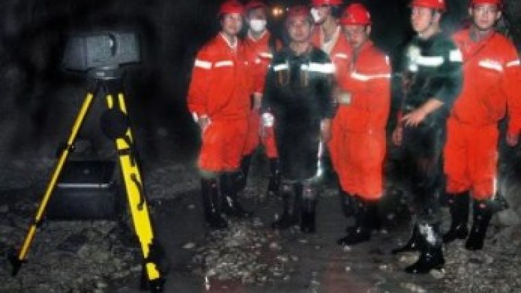
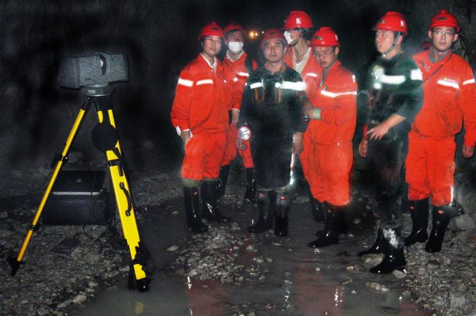
During a one-year project, 20km of tunnels located 650m below the surface, in hot and humid conditions, were captured using a Trimble FX 3D scanner (Figure 1). This phase shift scanner operates at the medium range (depending upon reflectivity up to 100m) at temperatures varying from 5oC to 45oC. If offers millimetre-level accuracy. When exploring the full field of view of 360o x 270o, a single pass scan takes five minutes resulting in 65 million points. The tunnels are narrow, varying between 3 and 6m in width. Speed was crucial, as the measuring activities must not interfere with production. Using a combination of tripods, brackets and attachments, the scanner could be set up within a few minutes. Each scan required less than five minutes, and could be completed without levelling the scanner.
To ensure sound fits between successive scans, target balls were placed in the overlaps of the scans. They acted as tie points. To connect the scans to the mine’s coordinate system, points were marked on the tunnel walls such that they were visible in the scans. These marks were measured using reflectorless total stations. Rigorous error propagation based on least squares adjustment showed that one mark per four scans was enough to achieve the required accuracy for overall volume computations (uncertainty of <5%).
3D Models
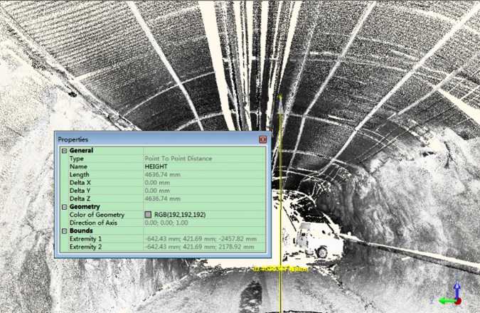
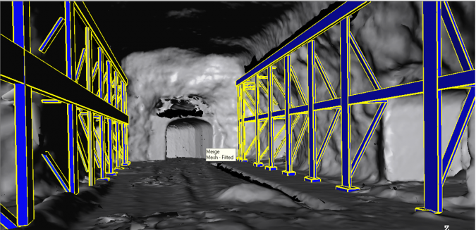
From the georeferenced point clouds, 3D models of the tunnels were created using Trimble RealWorks (Figure 2). To obtain a manageable dataset, the spacing of the original point clouds was altered from 1cm to 5cm. This adjustment with a factor of 25 did not affect the accuracy of the model nor subsequent calculations. The creation of a TIN of the tunnel walls and drifts required removal of unnecessary triangles and compensation for voids in the data that resulted from obstructions or interference during scanning. Next, pipes and conduits, ducts, drainage channels and other objects were manually extracted (Figure 3). Those objects had regular shapes and were modelled as 3D surfaces, tubes and other features. The resulting digital mine was far more accurate and complete than would have been possible using conventional methods. All data was transported to CAD software. Because the Trimble FX system can generate data for use in the mining package SURPAC, the data could be quickly integrated with existing software.
Applications
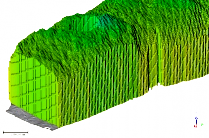
The digital mine provides up-to-date information on conditions, status and production quantities. One of the primary applications is computation of volumes, which requires definition of a reference surface located at the bottom of a tunnel segment. The ceiling is inspected on planar shapes which are modelled as small squares. Each square is projected onto the reference surface, resulting in cuboids of which the volumes can be calculated (Figure 4). Reducing the size of the squares corresponds to a denser sampling of the ceiling and thus increases precision of the volumes. The digital mine also enables comparison of the as-built tunnels against the original design, and detection of potential safety issues due to deformation or subsidence. Furthermore, the digital mine makes it possible to establish a detailed model of the ore body and a 3D model of the tunnels for trackless mining machines. By comparing the digital mine with the design, it is possible to monitor whether progress is being made according to plan, to visualise areas of over- or underbreak, and to verify the volume of material moved.

Value staying current with geomatics?
Stay on the map with our expertly curated newsletters.
We provide educational insights, industry updates, and inspiring stories to help you learn, grow, and reach your full potential in your field. Don't miss out - subscribe today and ensure you're always informed, educated, and inspired.
Choose your newsletter(s)


