3D Modelling of Fez
A Model from Aerial/Terrestrial Imagery and Topographic Maps
The ancient imperial city of Fez, Morocco, is an important tourist attraction and has been listed as a UNESCO World Heritage Site since 1981. The layout of the city is complex, which presents challenges in terms of 3D modelling. Here, the authors discuss a pilot aimed at creating a 3D model of Fez using topographic maps and aerial and terrestrial imagery. Overlapping 1:4,000 aerial images were used to create a digital surface model (DSM) and orthoimages. Orthoimages and topographic maps were used to manually delineate the footprints of buildings, roads, rivers and suchlike. Terrestrial imagery of single buildings from multiple viewpoints was captured with a digital camera to enable draping texture on the facades.
Founded in 789 and covering an area of 95 square kilometres, Fez has approximately one million inhabitants. The city is home to Quaraouiyne University which is the oldest university in the world (built in 857). In 1250 it replaced Marrakesh as the country’s capital, and remained so until 1912. Buildings, roads, trees and the terrain surface are the most important objects and features of a 3D city model. Potential uses for the 3D city model of Fez include urban planning, (flood) risk modelling, car navigation and transportation, positioning of mobile phones transmitters and solar panels, and visualisation of architectural designs and building restoration projects.
Data
The aerial survey was conducted and georeferenced by Cabinet Belmlih (GeoData) in 2007. Fez was recorded in seven north-south strips using a Zeiss RMK-A 15/23 film-frame camera with a focal length of 152mm. The 350 images (60%/30% overlap) at scale 1:4,000 were scanned with a ground sample distance (GSD) of 10cm. The GPS/IMU data collected on board combined with ground control points (GCPs) resulted in georeferenced images with a geometric accuracy of 1m.
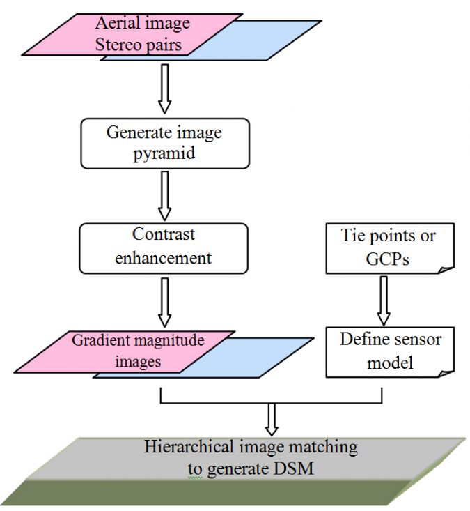
DSM Generation
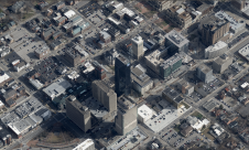
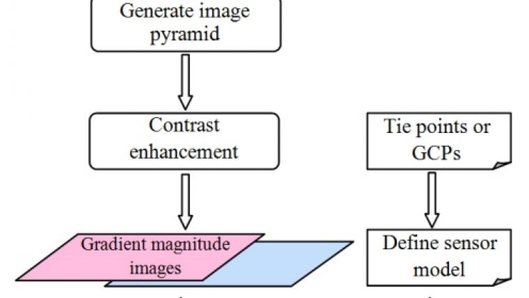
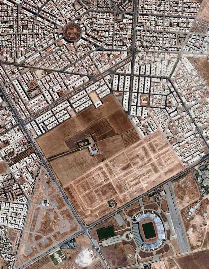
The Leica Geosystems LPS software was used to create the DSM. Figure 1 outlines the processing steps. LPS first requires selection of the sensor/camera type; definition of the sizes of the target and search windows, setting the threshold of correlation coefficient and other parameters; and input of the imagery to be processed and the coordinates of the GCPs and the automatically determined tie points. The quality of a DSM and derived products is largely determined by terrain roughness, point density, grid resolution or GSD of the DSM, and the interpolation method. Grid resolution and the interpolation method are interconnected since a DSM with a large GSD results in little detail whereas an interpolation technique such as Kriging may enhance the details. Additionally, the presence of height discontinuities affects the DSM quality; places with sudden changes in heights – such as where buildings rise up – may result in few, if any, matches or incorrect ones and hence low DSM quality. The geometric accuracy of the results has been checked using points located both in the centre of building roofs and on the ground (at a sufficient distance from facades to avoid any influence from the buildings). Before selection, visual inspections ensured that none of those points were outliers or mismatches. The checkpoints were then measured manually in stereo pairs. The root mean square error (RMS) was 22cm, i.e. around twice the GSD. Figure 2 shows an orthoimage and DSM.
3D Model
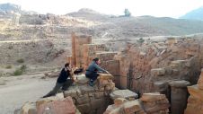
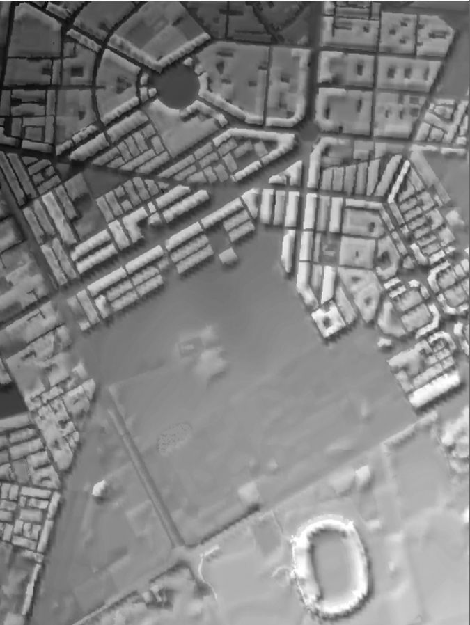
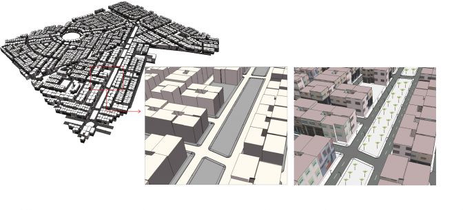
To create the 3D model from the DSM, the orthoimages, the topographic map and the terrestrial images, ArcGIS 10.2 was used together with CityEngine, which is 3D modelling software consisting of a full suite of tools for combining geodata from different sources. It enables the creation and editing of 3D buildings and road networks. Building footprints were manually delineated from orthoimages and topographic maps (Figure 3). Roads, rivers and land use derived from the orthoimagery were then draped over the DSM. Footprints were extruded in the third dimension using DSM heights resulting in a block representation (Figure 4). Next, texture from terrestrial images was projected on the facades of building models. Finally, trees, lampposts, road signs and other objects were added by a human operator.
Concluding Remarks
This pilot was the first phase of a project to create a 3D model of the entire city of Fez. The model will not only support general planning, monitoring and navigation tasks but will also help to preserve the heritage of the historical city.

Value staying current with geomatics?
Stay on the map with our expertly curated newsletters.
We provide educational insights, industry updates, and inspiring stories to help you learn, grow, and reach your full potential in your field. Don't miss out - subscribe today and ensure you're always informed, educated, and inspired.
Choose your newsletter(s)