Automated mobile system for mapping mine shafts
The benefits of laser scanning
Read about this automated mobile laser scanning system developed for mining. It facilitates fast and precise measurements to produce a 3D model of the mine shaft for further analysis.
Mine shafts are governed by special rules, often difficult to access and known for their unfavourable conditions for measurements. A mine shaft is of strategic importance for the proper functioning of the mine in terms of air ventilation, transport of people and material extraction, for example. Therefore, not least for safety reasons, mine shafts require regular inspections and surveys. For this purpose, the company SKALA 3D has developed an automated mobile laser scanning system as a mining survey system (MSS) which facilitates fast and precise measurements. The result is a comprehensive 3D model of the mine shaft ready for further analysis.
Mobile laser scanning technology is developing dynamically in the mining industry. The current choice of laser scanners ranges from high-precision panoramic scanners to handheld scanners and backpacks based on SLAM algorithms. There has been extensive research and investigation into the use of this type of technology in surveying mine shafts in recent years. However, due to the characteristics of the object and the lack of GNSS satellite signal coverage, the task has not been easy.
To calculate an accurate trajectory and consequently reconstruct an accurate 3D point cloud of the shaft, SKALA 3D has developed a methodology composed of:
- Initial trajectory estimation based on Kalman Filter incorporated for IMU data processing
- Calculation of relative poses (position and orientation) between consecutive trajectories based on an Iterative Closest Point algorithm when processing the Lidar point cloud
- Refinement of final trajectories based on a Graph SLAM algorithm incorporating all the poses of the trajectories (vertices) and the relative poses (edges)
- Fusing georeferenced data into trajectory refinement.
Since the design of the SKALA 3D MSS assures an overall 360-degree (panoramic) Lidar field of view, the calculation of relative poses can be done in six degrees of freedom.
Challenges addressed
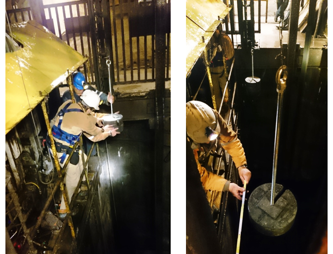
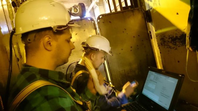
Three challenges are addressed: 1) automation of the shaft survey, 2) increasing the safety of mine surveyors, and 3) decreasing the cost of the survey by shortening the overall inspection time. The introduction of the appropriate technology made it possible to reduce the total working time of the mine surveyors and to minimize their exposure in the light of the shaft, in particular outside the cage. In other words, inspection using the MSS is not only faster but also enables safe operation on the inside of the cage (see Figure 3), which is impossible to achieve with the classical approach.
In addition to hardware challenges, there are also challenges in the amount of acquired data. Large numbers of mobile scanning surveys at low speeds generate large amounts of data, which calls for a lot of computational power. The parallel processing of orthogonal computational subproblems can thus improve the overall performance. Needless to say, this requires significant investment in hardware and software to facilitate efficient and reliable processing and alignment. But despite all these difficulties, there is currently no better, faster and equally precise technology on the market for the spatial inventory of mine shafts.
Mining survey system (MSS)
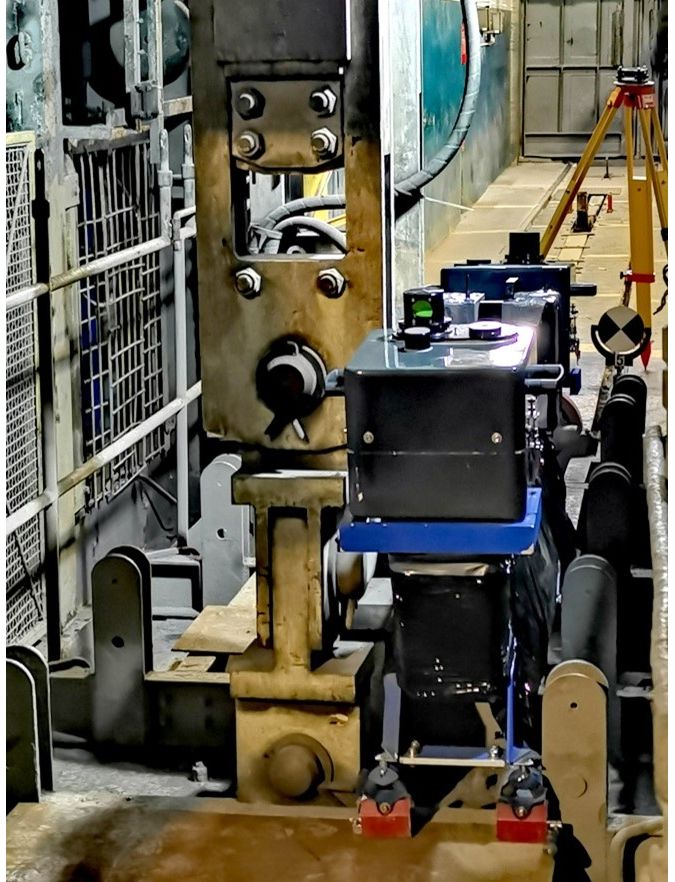
The whole technology is based on terrestrial laser scanning and measurements using a high-precision inertial measurement unit. The rigid measuring platform has also been fitted with a set of vibro-isolator systems which prevents vibrations ascending from the moving cage and improves the quality and accuracy of the measurements. The effect of this vibro-isolator system can be likened to the suspension system on a traditional road survey vehicle – it makes the trajectory smoother and therefore the IMU readings more reliable. The end result is a calibrated system, which can supply complete spatial data in a short time (just a couple of hours).
The system includes software to control and post-process the data. The precision in a single measurement horizon is 2-3mm. Evaluations during many shaft surveys have shown that, thanks to the Graph SLAM algorithm, the accuracy of the position of the point on the thousandth metre below ground is up to 10 centimetres (average 5-6cm). Although some hardware/software components are already in use in other applications, this hardware setup and overall design of the system is unique on a global scale. For example, the mechanical design (placement of the Lidar scanners resulting in a panoramic view), the vibro-isolator systems and the dedicated mounting components make the system easier to deploy in extremely demanding environments. Industrial magnets allow for fast installation on the roof of the cage. Moreover, the automation of the entire shaft survey process reduces the manual intervention, thus adding significant value in terms of operator safety.
Measurement characteristics
The measurement characteristics for the cage/skip at a speed of 0.5m/s are as follows:
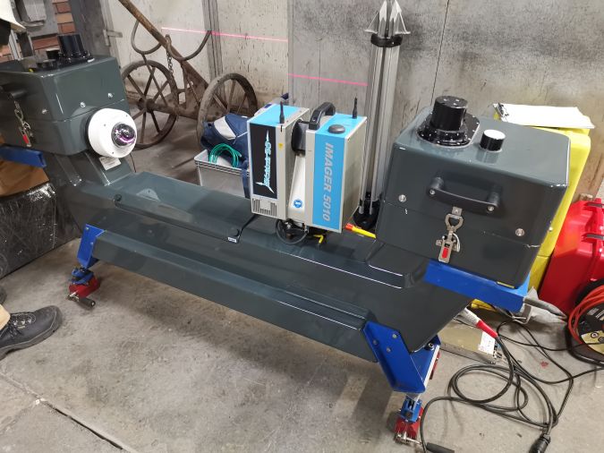
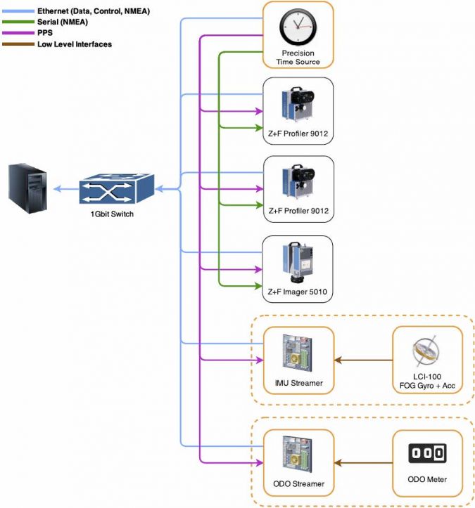
- Point cloud profile every 2.5mm from two Z+F 9012A profilers and one Z+F 5010X imager
- 2 x 200 profiles per second from two Z+F 9012A profilers
- Measurement of over 1 million points per second from all lasers
- IMU readings at 450Hz frequency
- The total ride time (down and up) in a 1,000m-deep shaft is approx. 1.5-2 hours (including additional time for setup, warm up and other deployment activities).
The cage or skip carrying the MSS can travel at a speed of between 0.1 and 12m/s. The impact of the speed on the Graph SLAM algorithm is minor due to the panoramic field of view of the entire Lidar setup. It is evident that higher speed will result in a lower resolution of the final 3D point cloud from the direction of motion. For this reason, an operational speed of 1m/s is preferable as a compromise between the measurement time and the resolution of the resulting point cloud.
Differences between traditional and mobile measurements
The main factors determining the choice of technologies used in mine shafts are time and safety. The inspected shafts ranged from 650m to 1,100m in length/depth. In classic geodetic surveys using the traditional method, surveying 1,000m of shaft usually takes three to five shifts (24-40 hours), depending on the measurement specifications. Regardless of whether a mechanical plumb line is lowered or laser plumbing is used, the surveyor has to stop every few metres and make several offsets. This means that only selected points are measured, plus it is a time-consuming task. In addition, the classic approach requires the continuous presence of people in the shaft, which poses a risk in terms of operator safety – especially because they often have to work outside the cage (see Figure 3). However, the biggest downside for mine owners of the traditional approach to measurements is that it interrupts the extraction of materials (known as ‘spoil’). In the case of the excavation shaft, every hour of downtime is a huge cost and this can cause significant financial losses for the mine. Needless to say, it is crucial to reduce this time from an economic perspective, and that was the main motivation behind the development of the MSS.
In fact, mobile laser scanning can reduce the time of the inspection by at least 50% and as much as 70% compared to traditional technology. Depending on the scope of the work, a complete survey takes just one or two shifts (8-16 hours). The technology is fully automated, which means that the involvement of the human operator is limited to the plumb lining (if necessary). For safety reasons, the MSS is operated from inside the cage.
The entire shaft image (point cloud) is acquired in just a couple of hours. Many different options for monitoring and comparing the state of the object are possible. Most importantly for mine owners, the cost of surveying the shaft using the MSS is considerably lower than the cost of the shaft being out of action for some time.
Possible analysis scenarios
The complete and accurate geometrical and photorealistic documentation of the shaft casing and its construction elements allows for a wide spectrum of analysis scenarios. For example:
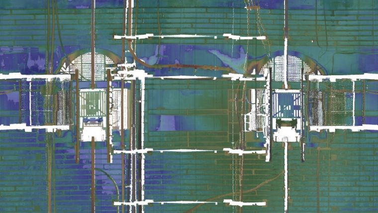
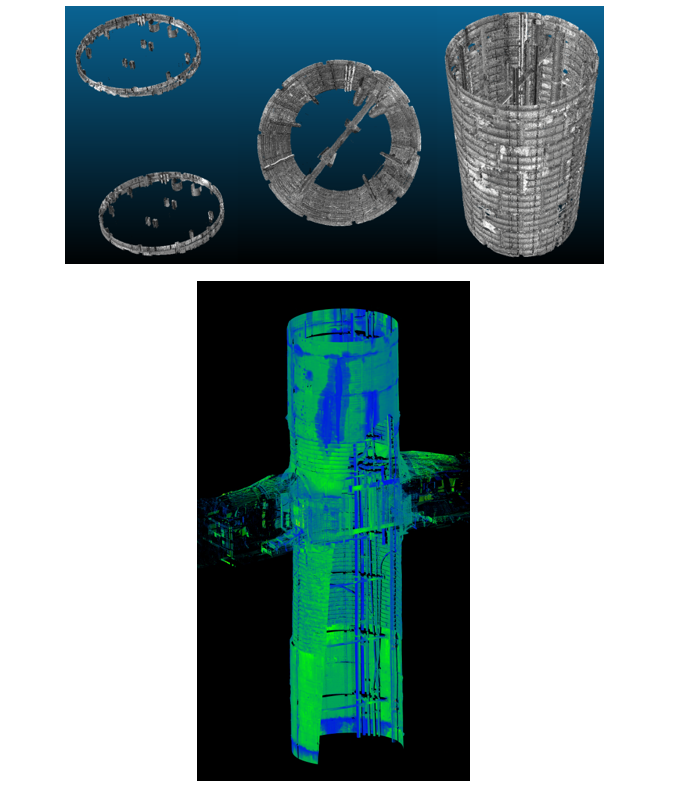
- Full 3D model of whole shaft pipe
- Documentation and monitoring of damage and physical changes, including deformations
- Possibility to design the location of new devices, e.g. pipeline, air conditioning
- Designing the renovation of selected places in the shaft based on one measurement
- Collision control during transport of large-dimension objects (machines)
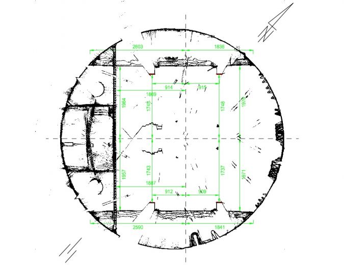
- The possibility of dimensioning on cross-sections anywhere in the shaft
- Verticality and straightness of the shaft and its components (shaft guidelines).
Conclusion
As shown above, the MSS automatic shaft measurement system works well in real life. The point cloud resulting from laser scanning is of good quality and requires much less work on-site than the classic approach, thus significantly reducing the overall costs for the mine owner. The efficiency of mobile laser scanning is much higher than conventional methods, without the inconvenience and safety problems associated with the work of mining surveyors in the shaft. In view of all these aspects, the authors maintain that automating mine shaft surveys can efficiently increase operator safety and reduce the inspection time, resulting in a cost-effective solution.
The MSS in practice
The measurement process and the methodology of the procedure are closely related to the scope of the work (elements to be measured). For example, determining the verticality of the shaft requires a different approach than merely measuring the geometry of the shaft lining and its construction elements. In order to obtain data in a specific geodetic coordinate system, it is necessary to perform georeferencing surveys on the geodetic control network points as for classic geodetic measurements or terrestrial laser scanning. Entire data registration process relies on a panoramic field of view, thus vertical and horizontal 3D landmarks (typically corners) contribute into Graph SLAM alignment. All trajectory nodes are considered as vertices (optimized parameters) and thanks to the Iterative Closest Point procedure it is possible to calculate relative poses between landmarks (and therefore relative poses between the trajectories). The alignment algorithm process all this information to minimize point-to-point Euclidean error. If georeferenced data is available, such additional landmarks are fused with other observation equations assuring global accuracy of the final 3D point cloud. Regardless of the purpose of the scan, the mining survey system is placed on the roof of the cage or skip. After setting up the measurement configuration, it is ready to scan. The system is fully automatic as an independent measurement instrument, so it does not require any additional effort. The post-processing procedures enable the fusing of additional georeferenced data if available.
The speed of the cage/skip passing through the shaft is selected depending on the desired vertical resolution. The operational speed is usually in the range of 0.5-1m/s. Typically, the measurement begins at the top of the shaft tower and ends at the lowest point in the shaft that can be reached through the cage. The scanning takes place when riding both down and up. The number of passes (surveys) depends on the geometry of the shaft. To cover the entire field of view, it is necessary to change the mounting position of the MSS on the cage/skip since many elements of the infrastructure (e.g. robes, etc.) could introduce blind spots in the final 3D point cloud. Since there are usually two cages, the total number of surveys is typically four (one down and one up from the outside of each cage). For a mining shaft with a depth of 1,000 metres, one measurement (survey) using the MSS at a cage speed of 1m/s takes 1 hour (up and down plus additional time for setup and the assembly of the scanning platform on the cage roof). Such a measurement configuration results in the average resolution of points on the object of 3x3mm. The global accuracy of the final 3D point cloud is less than 10cm at a depth of 1,000m. The relative accuracy between point clouds for different runs is 2-3mm.

Value staying current with geomatics?
Stay on the map with our expertly curated newsletters.
We provide educational insights, industry updates, and inspiring stories to help you learn, grow, and reach your full potential in your field. Don't miss out - subscribe today and ensure you're always informed, educated, and inspired.
Choose your newsletter(s)


