Autonomous 3D Modelling of Indoor Spaces
A Comparison of Mobile Indoor Scanning Methods
Mobile scanning can be an equally accurate yet more cost-effective solution than traditional terrestrial laser scanning done with tripods. To succeed, however, mobile scanners not only require a suitable combination of sensors, but also reliable and continuous knowledge about where the scanners are located and the direction in which they are pointing during scanning. There are multiple ways to achieve this, which has led to the development of various scientific and commercial solutions. This article compares several mobile scanning solutions for 3D modelling of indoor spaces and highlights their strengths and weaknesses.
In modern society, people tend to spend more time inside buildings than outdoors. Nevertheless, indoor spaces are – by far – less digitised than Earth’s surface. Modelling more indoor spaces from 3D measurements would satisfy many needs, and especially so if those measurements could be done rapidly, cost-effectively and accurately. Mobile scanning is a promising technology in this context.
Raw materials
Point clouds are the raw materials for 3D models. Mathematically, a point cloud is a set of points in a three-dimensional (3D) coordinate system. These points can be obtained from digital imagery or with laser scanning. In the case of imagery, prominent solutions use structure from motion (SfM) or its real-time variant, visual simultaneous localisation and mapping (SLAM). The structure, i.e. the geometry of indoor spaces, is triangulated from digital images visualising the same spots from different perspectives that can be acquired during motion. However, due to challenging lighting conditions and the scarceness of textures in indoor spaces, laser scanning appears to be the most promising approach so far.
Terrestrial laser scanning
Points are obtained from range measurements by the laser. The laser scanner emits a beam that is reflected with a revolving mirror to obtain a two-dimensional (2D) profile from the surroundings. If this 2D scanner is then simultaneously rotated on top of a tripod, it performs a 3D scan of the environment. Currently a single terrestrial laser scanning (TLS) scan is the most precise way of acquiring a dense point cloud of the surrounding environment. Due to occlusions, however, several scanning locations are needed – even in a relatively simple space – to achieve full coverage. It is possible to combine multiple tripod scans by using human-deployed scan targets in the field and software automation in the post-processing phase, or simply human intervention in the latter. Either way, this involves a considerable amount of manual labour.
Mobile scanning
Mobile scanning is faster than any scanning done using tripods and therefore provides more cost-effective solutions. There is a caveat, however: the range measurements cannot be used on their own. It is also necessary to know from where the measurements were taken, and pointing in which direction. If the scanner is sitting on top of a tripod, the pose of the scanner (its position and attitude) are usually known or can be determined easily. Scanning and moving at the same time, however, reduces point cloud accuracy because the scanner pose estimate is less accurate. After going mobile and having traded off some point cloud accuracy in favour of time savings, the challenge is how to reclaim some of this lost accuracy to reach the accuracy level that is required for indoor modelling.
Localisation
At the heart of a precise 3D point cloud is an accurate trajectory. Determining the pose of the scanner must be both continuous and reliable. Satellite signals typically do not reach inside buildings, which means that the trajectory must be obtained relatively, by correlating newly obtained measurements with those obtained earlier since the start of the scan. In other words, the question of the scanner’s location is answered by observing that the overlap of the data is coherent with itself. For example, when a wall is scanned twice, this data must be coherent with itself. This is the principle of SLAM.
Determining the pose requires a 3D Cartesian vector and a 3D angular vector. In other words there are six unknowns, or six degrees of freedom. These do not need to be solved at the same time. One trick to simplify the problem is to omit the height direction. Some methods use this and some do not; some use it as an initial estimate.
Comparison
There are thus multiple ways to localise the scanner. Not only are there different combinations of multi-sensor systems that can be assembled, but there is also a sandbox form of freedom in incorporating the algorithmic side, which deeply affects whether a certain approach is successful (please note that SLAM refers to a range of tools and methods, and not to any specific data processing algorithm).
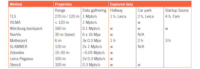
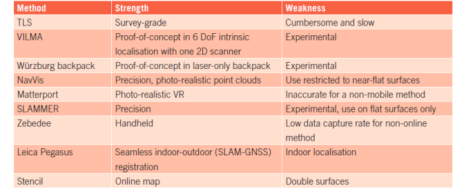
In the scientific paper on which this article is based (Comparison of the Selected State-Of-The-Art 3D Indoor Scanning and Point Cloud Generation Methods, see ‘Further Reading’), to evaluate the strengths and weaknesses of these different methods the authors analysed the performance of eight different scanning methods and compared them against a reference taken with a survey-grade TLS. Three different test sites were used, and the evaluated methods are listed in the table below.
Dimensions
When choosing the method to localise the scanner it is important to take into account the physical properties of the environment. The results of the comparison study show that estimating the scanner pose in two dimensions – as is done by the NavVis system – only produces less error in the 3D point cloud provided that the floor is flat. However, a wheeled platform such as NavVis is not navigable in all indoor spaces.
A scientific backpack from the University of Würzburg employs one horizontal 2D laser scanner to perform a more reliable localisation in two dimensions. Then the data from another scanner operating in 3D is used to calculate vertical corrections to recover the six degrees of freedom. Despite its potential, no commercial system uses this approach yet.
Theoretically, localisation may begin in an even-lower dimension. The scientific device VILMA, from Aalto University, makes use of a theoretical solution to obtain the trajectory first in 1D, and then employs SLAM to expand the trajectory estimate to two, three and finally six degrees of freedom.
For versatile needs in staired or otherwise complex indoor environments, one valid commercial option is ZEB1 from GeoSLAM or one of its successors. Because the problem of determining the pose as a function of time is quite challenging, ZEB1 uses an inertial sensor to find a working estimate for the pose that can then be refined by correlating the measurement data.
Robustness
In addition to software development in mobile laser scanning, hardware is also improving. Localisation robustness is gained through multi-line scanners. In contrast to current 2D laser scanners that produce just one row of pixels, these multi-line scanners capture whole images, which increases geometrical constraints for a more accurate trajectory computation. For example, Kaarta’s Stencil solution employs a 16-row Velodyne for increased robustness. The product is a strong candidate for indoor 3D measuring.
Sensor Fusion
Leica Pegasus:Backpack is a product available from Leica Geosystems. It mounts two Velodyne-16s to a backpack with a GNSS receiver for seamless indoor-outdoor positioning. However, it would seem that the multitude of sensors impacts somewhat on the overall performance, leaving Pegasus behind ZEB1 and Stencil in terms of point cloud accuracy.
Combining both worlds
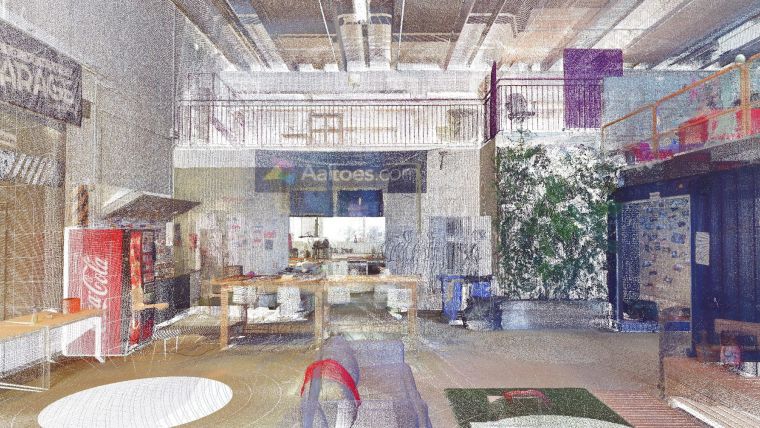
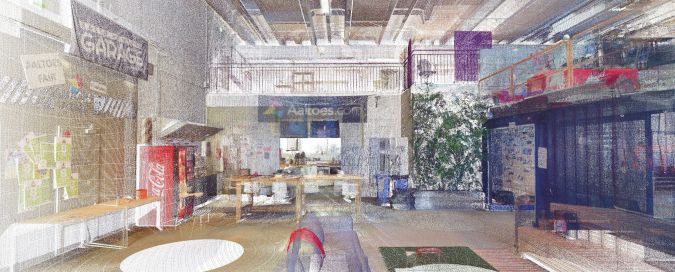
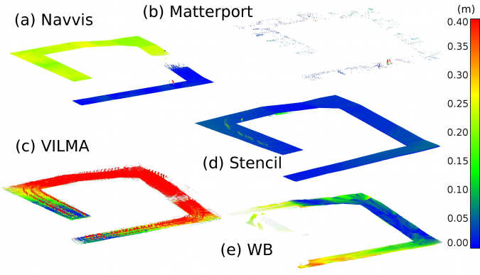
Matterport is a product that lies between the two worlds of terrestrial scanning and mobile mapping. It combines a tripod-mounted depth camera system with cloud services that offer automated data post-processing. The scarcity of points in Figure 3 does not indicate that there is something amiss. On the contrary, the cloud is already thinned for 3D modelling purposes, and its accuracy – although less than that delivered by ZEB1 and Stencil – is undoubtedly adequate for various applications. On the downside, the 6-metre sensor range forces the user to do a lot of footwork.
Indoor challenges
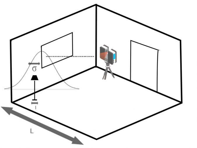
Indoor spaces are challenging due to the fact that features span various length scales. For example, in the sketch in Figure 2, the width of the lamp leg has an entirely different length scale than the width of the room. The challenge is that the scanning method precision should be sufficient to capture the smallest sub-centimetre features while simultaneously being computationally able to track spaces spanning hundreds of metres. On the one hand, if the precision is not sufficient, the smaller features are incorporated into larger ones in the measurements, deforming their shapes. On the other, if the method attempts to capture spaces spanning large distances, there needs to be an efficient way to compress the data.
Results
There are multiple ways that may be used to differentiate the methods in terms of point cloud accuracy and precision. Differences can be sought between two point clouds A and B, between two similarly cut subsets of these point clouds, or between control points. In this comparison the authors have used the first two approaches. Figure 3 shows a subset of a point cloud, i.e. a ramp floor, captured in a car park. Note how the closest point accuracy behaves for different methods.
Conclusion
Relative positioning is mundane in geomatics for 3D point clouds obtained with a tripod and scan targets. With a continuously moving scanner, however, the situation is more complicated. Combining the best solutions from the current state of the art should provide an answer for the multitude of needs in 3D indoor modelling. Meanwhile, the best scanning accuracy is obtained from the wheeled NavVis platform, with Stencil being a good portable solution.
Application examples
3D point clouds of indoor environments offer a range of applications. During construction, the progress of the work can be followed digitally. Scanning updates keep track of completed phases and lead to automated updates for project schedules and delivery order dates, while also redefining critical paths so that resource reallocations may be suggested. Georeferenced verification of completed construction phases reveal possible problems and any need for revisions. In addition, construction permits issued by city officials become digitally manageable through building information modelling (BIM). The final checking of the built result can be digitally compared to the approved plans if the just constructed indoor spaces can be scanned. Digital archiving of the plans reduces public spending and improves archive usability. The as-built data is ready to be applied for renovation plans. Sustainability is achievable through thermal models of buildings that reveal the extent and source of heat losses.
Further Reading
Lehtola, V. V., Kaartinen, H., Nüchter, A., et al. (2017). Comparison of the Selected State-Of-The-Art 3D Indoor Scanning and Point Cloud Generation Methods. Remote Sensing, 9(8), 796.

Value staying current with geomatics?
Stay on the map with our expertly curated newsletters.
We provide educational insights, industry updates, and inspiring stories to help you learn, grow, and reach your full potential in your field. Don't miss out - subscribe today and ensure you're always informed, educated, and inspired.
Choose your newsletter(s)


