Capturing Scenes with Lidar
Technology in Focus has on three occasions (February 2005, 2006 and 2007) addressed laser and terrestrial Lidar, also called 3D-laser mapping. The first two articles treated the laser component, and the last was on software processing to extract meaningful object models from point-clouds. This fourth article focuses on precautions required when capturing scenes. Terrestrial Lidar: I know what it is, I know what it does, but how do I capture a scene?
Vendors of terrestrial Lidar scanners often proudly present the operation of their instruments in the field as “a piece of cake”. And they are right; it is convenient. One just needs to place the instrument in front of the object, level it roughly, enter the area and push the button. It’s as simple as that. Or at least, as far as the instrument side of the survey is concerned. But the snag lies not in operating the instrument but in the prelude to this, and in scene monitoring during capture.
Before placing the instrument the operator has to ensure that no objects intervene between instrument and scene that might occlude essential parts of it. This means no cars, lampposts, traffic signs, vegetation, people or donkeys. No ‘alien objects’, as Prof. Heinz Ruther called them in his discussion of the challenges posed by terrestrial scanning of heritage sites (GIM International May, 2007, pp 14-17). Potential sources of failure may also be hidden in the scene; lapses may result especially from the reflectance characteristics of the surfaces of objects. Hitting a surface, a laser beam may interact with it in three ways: it may be reflected, absorbed or transmitted. Only reflected beams will reach the instrument and thus be of use, but one reflection is better than another. Ideally, a surface behaves as a diffuse reflector, so that the resulting reflections are of like strength in all directions. In this case most of the signal returned from the surface reaches the instrument. But when parts of an object have a specular surface the reflection is deflected and little or no signal is returned to the instrument. Therefore mirrors, shiny metal and brackets of neon lights present in the scene have to be removed or covered. Signal strength, recorded in addition to time of flight of the laser beam, provides the operator with a helpful means of detecting lapses in reflectance during processing of point-clouds.
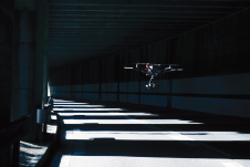
Laser beams may be transmitted through windows; this can happen, for example, with buildings, and results in the recording of objects on the other side of the glass. To avoid problems in reconstructing the final scene, windows have to be covered, or special caution must be exercised in processing the point-cloud. Highway police, when using scanners to record the site of an accident, spray special powder on car windows to prevent the scanner “looking” through them. Indeed, we live in a dynamic world full of people continually on the move, so that pedestrians tend to cross a scene whilst it is being captured, and the same is true of animals, cars and bikes (Figure 1). The surveyor must thus close off the scene area to all traffic before pushing the button. This might sound self-evident, but how often are ground-control points for aerial surveys invisible because they lie beneath trees or just a few metres from a thirty-storey building? And in practice closing the scene to moving objects often proves much more problematic than it sounds.
In addition to covering objects and preventing things crossing the scene, the surveyor also has to place and identify objects in it prior to pushing the button. Objects may be markers, such as nails, or marked existing points, such as sharp corners. They are used as control points, necessary for the conversion of range data to X,Y,Z coordinates in a national or local reference system. The location of the points has to be selected with care and unambiguously indicated to avoid mistakes. Most commonly, four control points are used at the edges of the scan, although three is enough for geo-referencing; the fourth is used for reserve and check. Large objects require scanning from several positions, and adjacent scans have adequately to overlap. Once a control point has been identified in one scan, identification in the overlapping scans can be done semi-automatically.
The products generated from Lidar scanner point-clouds are used by a multitude of professionals such as architects, chemical engineers, construction and mechanical engineers. Every profession has its jargon, and Babel, a confusion of tongues, may cause discrepancies to arise between the product produced by the surveyor and his client’s wishes. For example, “cross-section” is a term used by all the above named professionals, but each represents it completely differently. A surveyor needs to speak all tongues.
Acknowledgements:
Thanks are due to Leica Geosystems, and to Ron Rozema, Lidar surveyor with Fugro.

Value staying current with geomatics?
Stay on the map with our expertly curated newsletters.
We provide educational insights, industry updates, and inspiring stories to help you learn, grow, and reach your full potential in your field. Don't miss out - subscribe today and ensure you're always informed, educated, and inspired.
Choose your newsletter(s)


