Comparing DIM and TLS
Capturing an archaeological site in Oman
Photogrammetry and terrestrial laser scanning (TLS) are both proven technologies for archaeological documentation. Dense image matching (DIM) has evolved rapidly since 2010 and enables the highly automatic creation of detailed point clouds from overlapping imagery. How well does DIM perform for archaeological applications compared to TLS? The authors go in search of an answer.
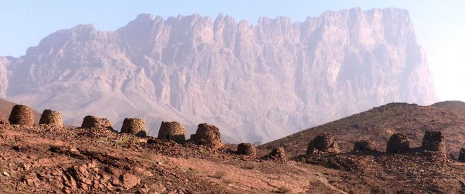
The necropolis of Al-Ayn in Oman (Figure 1) comprises 19 well-preserved tombs of between 2m and 4m in height which extend over 130m (Figure 1). Since 1988 the tombs have been a UNESCO World Heritage site. The exterior diameters of the slightly conical tombs range from 3m to 6m, and the interior diameters from 1.5m to 2.5m. The building material consists of quarry blocks of varying sizes. The photogrammetric and terrestrial laser scanning (TLS) surveys, carried out in February 2014, were aimed at documenting the necropolis and enabled a comparison between dense image matching (DIM) and TLS. Such a comparison is interesting as today’s cameras are light and thus more easily portable than TLS equipment, and because the processing of imagery and creation of point clouds has become cheaper in recent years as a result of open-source packages. Furthermore, images can capture pottery shards, bone fragments and other small objects in great detail.
Conventional tools and accuracy
Photogrammetry and TLS have been used for archaeological documentation for many years. Nevertheless, conventional tools such as measuring tapes, folding rules, levels and simple theodolites and total stations are still commonplace. The data captured by conventional tools is mainly used for creating orthogonal views, vertical sections and maps. No unified accuracy requirements have been defined by archaeologists. The authors’ co-workers, specialised in archaeology, derived accuracy measurements from a project in which object points were measured with a total station and subsequently georeferenced. The coordinates were mapped at scale 1:100. Vertical sections, drawn in the field and manually digitised, were mapped at scale 1:50. This exercise, which contains several intermediate steps, resulted in an accuracy of 3.6cm. Both TLS and DIM enable digital processing without intermediate steps which may reduce accuracy. Additionally, their accuracies have proven to be significantly higher compared to conventional tools. In consultation with the archaeologists, the accuracy standard was set to 2cm.
TLS
TLS point clouds were acquired using a Zoller and Fröhlich Imager 5010. The capturing of the 19 tombs both on the outside and inside was done from 91 TLS positions. The exterior of each tomb was captured in seven scans with an average resolution of 6mm and the interior in one or two scans with a resolution of 4mm. The maximum range was 25m to the exterior of the tombs, and 2.5m for the interior. The point clouds were coloured from images taken using a Canon EOS 500D DSLR camera with a 10mm fisheye lens and mounted on a panoramic tripod head.
Photogrammetry
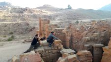
The interiors and exteriors of the tombs were recorded using a remote- controlled Canon D60 SLR camera, focal length 24mm, mounted on a tripod to ensure stability. With a minimum overlap of 80% in all directions every point in the scene was captured in at least four images. The exterior of each tomb was captured by an average of 56 images taken from a distance of 5m. The interior required 93 images per tomb taken from a distance of 2m above the tomb. In total 4,222 images were taken, which were processed using PhotoScan from Agisoft LLC. Compared to similar freeware, such as VisualSFM, Photoscan produces denser point clouds and is easier to handle. The calibration parameters, determined using a test field, differed by at most 1mm at selected object points from the parameters calculated in the simultaneous calibration of the bundle block adjustment. Therefore, the latter was used. On average, the image scale was 1:200. The image measurement accuracy of signalled tie points was 1.8 microns and the internal object accuracy was 0.3mm. After 3D similarity transformation (7 parameters: scale, 3 translation and 3 rotations) the two point clouds showed a maximum deviation of 2.3mm at the control points, which far exceeds the accuracy standard of 2cm.
Georeferencing
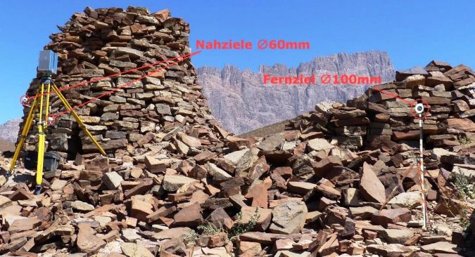
To enable the comparison of DIM and TLS point clouds and derived products, a network of 10 points was created around the tombs using a total station. The local 3D coordinates were transformed to a geodetic reference system using four GNSS control points. The coordinates of the TLS stations and control points were connected to this geodetic reference system through a total station resulting in a planar accuracy (1 sigma) of 5mm and a height accuracy of 2mm. The positions of the TLS stations were also determined using a referencing set by Laserscanning Europe GmbH (Figure 2). The spheres with integrated prisms have been designed for quick and flexible scanning without targets. The centres of the spheres were determined with a total station. Two spheres – diameter 6cm – were mounted on the legs of the tripod and a third one with a diameter of 10cm was positioned at a distance of 10m-15m from the scanner. The workload of referencing with spheres is 50% less than when using signalised targets, without significant loss of accuracy. Since the set of spheres could not be used inside the tombs due to space limitations, the positions of the TLS were measured there using a total station and the coordinates of at least three reference points were determined additionally.
Comparison
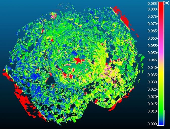
Five tombs with differing features and spread over the area were selected for comparing the DIM and TLS point clouds using the open-source software CloudCompare. TLS point density becomes coarser towards the edges of the scan, an effect images suffer less from. TLS point clouds show data gaps in regions of scan shadows; the DIM point cloud is more complete because of the 80% overlap. Due to shadows present in the joints of the quarry blocks, DIM could only detect a few points feasible for matching. In contrast, TLS is not affected by lighting conditions.
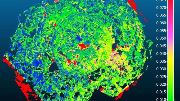
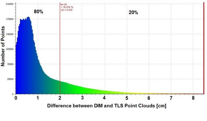
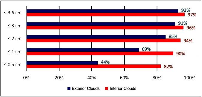
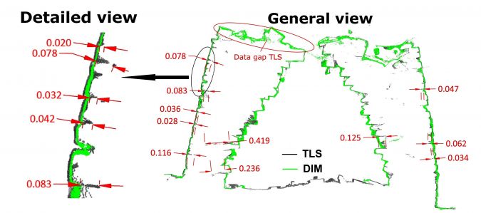
Nearly 80% of the differences are less than 2cm and the number of major deviations tends asymptotically to zero (Figure 3). Large deviations are due to TLS scan shadows (red in Figure 3). Differences larger than 8.5cm, a threshold found empirically, were indicated as data gaps. There are large differences in the joints between quarry blocks. To assess the deviations they were grouped in classes (Figure 4). About 90% of the points inside the tombs differ by less than 1cm as the scanner and camera could capture the inside of tombs at very close range. The differences of the top part are less than 1cm for 69% of the points and less than 3cm for 90% of the points. Differences larger than 2cm occur only in areas of data gaps and when the surfaces of blocks and joints are poorly illuminated. One remedy would be to improve the planning of the survey. Vertical sections show the origins of the differences between the TLS and DIM point clouds (Figure 5). In the DIM, point cloud surfaces are smoothed. The time spent on field work and data processing workload are similar. DIM requires one tenth of the financial investment of TLS and needs only basic photogrammetric knowledge, whereas proper planning and execution of complex TLS projects require at least six months’ training.
Evaluation of field work
The field work took 10 man-days. The most time was taken up by determining control points and imaging the top part of the tombs. An experiment with a camera mounted on a 4m-long pole produced poor results. Building scaffolding would have taken up too much time and exceeded the financial budget. A feasible alternative would have been to use a multicopter UAS as this technology produces fast and highly accurate results. However, the law restricted its use.
Acknowledgement
Thanks are due to the Institute for Ancient Near Eastern Studies (IANES) at Eberhard Karls University Tubingen for its cooperation.

Value staying current with geomatics?
Stay on the map with our expertly curated newsletters.
We provide educational insights, industry updates, and inspiring stories to help you learn, grow, and reach your full potential in your field. Don't miss out - subscribe today and ensure you're always informed, educated, and inspired.
Choose your newsletter(s)