Continuous Mobile Laser Scanning
Mobile Platform Terrestrial Lidar, IMU and GPS
Combining Terrestrial Laser Scanning, Position and Orientation Systems and GPS receivers into a mobile mapping system enables effective mapping of large and complex terrain. The authors tested a mobile mapping system at two sites: in an open pit mine, and along a road.<P>
Optech and Sineco have been developing a mobile mapping system, initially based on a platform combining the ILRIS-3D (Intelligent Laser Ranging and Imaging System), the Applanix POS LV (land-based vehicle) and GPS receivers. This new system, ILRIS-MC (Motion Compensation), can be installed on any mobile platform and performs fast surveys, generating point-clouds in real time in WGS84 coordinates.
Components
The integrated system generates a laser point-cloud, either through conventional scanning creating two-axis scans and intended for use on unstable platforms such as cranes and floating platforms, or through continuous horizontal and/or vertical scanning, intended for use on mobile platforms. The Applanix POS LV 420 contains an Inertial Measurement Unit (IMU), three accelerometers and three gyroscopes, which measure the acceleration and angular velocity needed to compute position, speed, acceleration, orientation and rotation. The system also includes a Distance Measurement Indicator (DMI), a wheel-mounted rotary shaft encoder for precise measurement of linear distances travelled, which enables reduction of IMU drift error during GPS outage. A POS Computer System in the vehicle is the central processing computer housing the GPS receiver, PCMCIA drive, data-processing and power-distribution units for all POS LV components. Two dual-frequency (L1/L2) GPS receivers provide geo-referencing: a ground-based receiver at a Permanent Network Station (PNS) and a mobile one (rover). Differential GPS (DGPS) processing is used for correction and refinement: data from the rover is processed in combination with data from the ground-based receiver. The PNS is usually set near or relative to a known Ground Control Point (GCP) close to the surveyed area and then used to determine GCP and correct mobile GPS receiver data during post-processing. Using DGPS can increase GPS accuracy to approximately 1cm.
Integration
Connectivity between the three systems is limited to synchronising the clocks between the instruments. In dynamic mode each system collects data independently. The ILRIS-3D time-stamps every event using its local clock, and then uses this time to establish the offset (recalculated every second) between its local clock and GPS time. In post-processing, the only two files required to generate motion-compensated data are (1) Applanix SBET (Smoothed Best Estimated Trajectory) containing trajectory and orientation over the duration of survey and (2) Optech ROW consisting of laser data, including range, intensity, angle and time. The final laser point-clouds are directly geo-referenced in WGS84 coordinates. To test its ability the integrated system was mounted on a van and two surveys were carried out, one in an open pit mine and one along a road.
Open Pit Mine
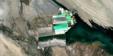
The goal was to survey the entire mine, account for all stockpiles, and generate a calculation of dig volume. An area of 600×500 metres was surveyed in thirty minutes and almost 19 million points collected, resolution approximately 10cm, at vehicular speed of 5km/h; the low speed was due to the rough and uneven gravel road. To meet requirements the final product was sub-sampled to a point-cloud of 50cm resolution. Based on the precision of the three instruments (ILRIS-3D at 7mm, POS at 3cm and GPS at 1cm), the overall accuracy was calculated to be 4cm. PolyWorks, a commercial software application, was used to process the data, carry out volume calculation and extract the final mesh and cross-sections easily in little time.
Single-lane Road
The goal was to obtain all details surrounding the road: the embankment, pavement, buildings, and other infrastructure elements such as bridges and roundabouts. The system surveyed the road, approximately 8km long, over thirty minutes and collected more than 9 million points. Density was 60points/m2, with the vehicle travelling at 15-20 km/h. Due to many GPS gaps and vertical walls adjacent to the road, final accuracy appeared no better than 5cm to 6cm. PolyWorks, in combination with AutoCAD and Autodesk Civil 3D, was used to process the data (Figures 5 and 6). This resulted in road mapping and CAD reconstruction of road geometry, cracking of road surface, major ruts in pavement and asphalt deformation, vertical and horizontal location of traffic signs, location and cross-section of road sections such as emergency lay-by, tunnels and bridges, and side vegetation and walls.
Concluding Remarks
Testing proved the viability of Continuous Mobile Laser Scanning. Improvements in ease of installation and use are anticipated with the advent of advanced solutions such as the recently unveiled Lynx Mobile Mapper.

Value staying current with geomatics?
Stay on the map with our expertly curated newsletters.
We provide educational insights, industry updates, and inspiring stories to help you learn, grow, and reach your full potential in your field. Don't miss out - subscribe today and ensure you're always informed, educated, and inspired.
Choose your newsletter(s)

