Data Integration for Coastal Surveying
Combining Laser Scanner and Bathymetric Sensor
When surveying the coastline, the integration of bathymetric (below sea level) and laser scanning (above sea level) data causes problems due to the different imaging properties. However, by ensuring that the different data sets have been accurately georeferenced and oriented, a complete and accurate model of the terrain above and below sea level can be obtained. This technique was employed to survey the area of Portovenere in Italy, including the San Pietro church located on a steeply sloping rocky promontory, with positional accuracies in the order of 5cm.
One of the biggest issues in coastline survey is the accurate combination of terrestrial and marine data. This problem is caused by several issues. Different data sources have different image resolution and accuracy. In addition, integrating data retrieved from different sensors at different times introduces problems with georeferencing. Codevintec Italiana and its partners have overcome these problems by merging terrestrial Lidar and bathymetric data in order to obtain a high-resolution three-dimensional (3D) model of the coast (see survey of Livorno Castle and harbour, GIM International, March 2007).
Integrated Approach
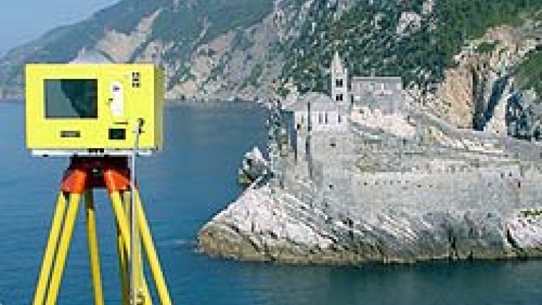
Recently, Optech laser scanners were updated to operate with position and attitude information. Codevintec equipped a vessel with a boat-mounted Optech intelligent laser ranging and imaging system (ILRIS-3D) to survey areas above water level. A SWATHplus-H wide-swath sonar system from Systems Engineering and Assessment Ltd (SEA) was also established to collect underwater topographic data. The combined GPS and inertial Applanix platform - position and orientation system for marine vessels (POS MV 320) - measured the position and attitude of the two sensors during the survey. This integrated approach allowed us to obtain a complete 3D model during a single survey, including locations that were impossible to reach from land. Trial surveys were carried out by the Italian Navy in Portovenere, Italy (Figure 1), around the area of the Church of San Pietro. The church, which sits on a rocky promontory, was built by the Genoese between 1256 and 1277 on the ruins of a Paleochristian church, which in turn was built over a pagan temple dedicated to the goddess Venus Erycina.
Data Acquisition
Since one of our goals was to compare results obtained using both static and dynamic Lidar, the site was surveyed over two different time frames using two different approaches. In 2006, the entire church exterior and interior were surveyed using the terrestrial laser scanner ILRIS-3D (static survey, Figure 2). The second survey, in the summer of 2008, involved two different sensors. The dynamic laser scanner ILRIS-MC (motion compensation) and bathymetric sonar SWATHPlus-H data sets were acquired at the same time. Both data sets were georeferenced and oriented using the Applanix inertial system. The 3D model of the entire bay above and below sea level was then integrated with the high-resolution scan of the church acquired in 2006.
Static Survey
Fifteen external stationary lasers were positioned around the church for a total of 32 acquisitions. An additional scan was also performed from Palmaria Island in order to improve the model along the south side. Three scans were acquired of the church interior. The pan and tilt technique allowed the entire 360° field of view to be measured. While the laser scanner survey was conducted by Codevintec, the Navy completed the topographic survey using a high-precision total station. Those points were used for the final georeferencing of the entire 3D point cloud. PolyWorks software from InnovMetric was used to align and georeference the point clouds and to create the triangulated model of the church. Z-Map software was used to create the orthophoto and the CAD model of the main façade (Figure 3).
Dynamic Survey
The Naval Hydrographic Office tested the integration of different sensors on the same boat in June 2008. Being able to scan from a boat allowed us to collect data along the southwest façade of the church (impossible during the 2006 static survey). The vessel followed several lines at a speed of 2-4 knots in order to cover the entire area at an optimal resolution. At the heart of our system is the Applanix POS MV, which acquired data at 100Hz in order to provide the necessary attitude corrections. It comprises three accelerometers and three gyroscopes, which measure the acceleration and angular velocity in order to compute all aspects of the boat motion: position, speed, tide, acceleration, orientation and rotation. Two dual-frequency (L1/L2) GPS receivers track and record the vessel's path. Differential GPS processing was used to correct and refine the georeferenced data. The position and motion data can be processed to increase GPS accuracy to approximately 1cm.
ILRIS-MC
The ILRIS-MC (Figure 4) offers several advantages compared with traditional survey techniques. Dynamic scanning is carried out quickly and efficiently, allowing previously inaccessible locations to be measured. The system records the Cartesian coordinates of every measurement, as well as the intensity of the beam, which is dependent on the target level of reflectivity. Two different ILRIS-MC surveys were completed. The first involved blocking one mirror and scanning vertical lines (yielding a resolution in the direction of the vessel dependent upon its speed). The boat was then anchored in front of the rock face and a pseudo-static survey was performed. This allowed the final resolution to be increased (to 1-2cm) and precise motion-compensated 3D data sets to be automatically generated.
SWATHplus
The SWATHplus interferometric technique can collect wide-swath high-resolution bathymetric data. It is especially useful in shallow water as data can be collected quickly. A high-frequency (468kHz) transducer was used to survey the seabed at depths of 2-25m, obtaining a resolution of 10cm. The technique measures range from timing and angle by comparing phases at vertically spaced transducer staves installed on the hull. The interferometric technology allows simultaneous collection of side-scan data at the same resolution as the bathymetric data. This allows a point cloud to be acquired with the same features as the laser scanner (range and intensity). The final output is a XYZ georeferenced point cloud grid.
Systems Integration
One of the biggest issues in this type of survey is the knowledge of the relative distances between every object. The POS has its own orientation and position inside the boat, and it is important to know the exact orientation and location of the ILRIS-MC and SWATHplus sensors relative to the POS. The connectivity between ILRIS-MC and positioning system is limited to synchronising the clocks between the instruments. SWATHplus received binary data directly from the positioning system. To regulate the two sensors with the POS, two different calibrations were performed for both ILRIS and SWATHplus:
- lever arm: relative position with respect to the POS (X, Y and Z); and
- boresight: angle orientation with respect to the POS (roll, pitch and heading).
Processing Data
The binary data collected by the POS were processed with the GPS reference data using POSPac software. The result is the smoothed best estimated trajectory (SBET) that is used as input to correct both laser and bathymetry data. The ILRIS-MC data were processed with the SBET using the parser software, inputting the previously calculated calibration file. The same SWATHplus software that was used to collect the bathymetric data was also used to process them, applying the observed motion, speed of sound in water and tidal data. The processed data were gridded and edited to create the final ASCII digital terrain model (DTM). PolyWorks software was used to integrate the three data sets
(ILRIS-3D 2006, ILRIS-MC 2008 and SWATHplus 2008), yielding a complete model of the Portovenere area (Figure 5).
Complete Data set
Both dynamic laser scanning and interferometric multi-beam allow large areas to be surveyed quickly with an absolute accuracy of about 5cm. Georeferenced data sets are automatically generated. In conditions where neither technology can operate independently, the two techniques provide a complete data set. This fusion of two methods generated a complete and accurate digital model of areas above and below the water level, a result that cannot be duplicated with any other topographical survey instruments. The georeferencing accuracy allowed these data to be integrated with the results of a static Lidar survey in order to increase the resolution of particular objects of interest.
Acknowledgements
Gratitude and thanks to Captain De Marte, the entire staff of the Nave Magnaghi, especially Captain Tozzi, and Mark Field.

Value staying current with geomatics?
Stay on the map with our expertly curated newsletters.
We provide educational insights, industry updates, and inspiring stories to help you learn, grow, and reach your full potential in your field. Don't miss out - subscribe today and ensure you're always informed, educated, and inspired.
Choose your newsletter(s)


