Digital twin supports accurate renovation planning
Mapping an operational medical clinic in 3D
Which challenges were associated with deriving a digital twin to support constructional changes at a 100,000m² health clinic in Germany, and how were they overcome?
Renovating existing buildings remains a challenging task for the construction industry since the work of planners is often hampered by missing, incomplete or out-of-date construction plans. In recent years, digital twins that are capable of depicting both the current status and future stages of a building have become a reliable source of information during the planning phase. This article outlines the challenging workflow of deriving an initial digital twin for a health clinic comprising approximately 100,000m² in support of subsequent constructional changes.
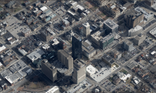
This digital twin project was conducted at a clinic on a medical university campus in Germany. The clinic, which has been in operation since 1987, is now due to undergo substantial core refurbishment of the eight-storey building. The renovation project is expected to take at least 17 years, including the planning stage, and the budget is a total of €590 million. In order to avoid cost overruns, and to stick to the building schedule as well as to maintain quality assurance, building information modelling (BIM) was chosen as one of the planning strategies.
The challenges of this project are manifold, ranging from the sheer size of the building to the high demands for accuracy due to the complex nature of the technical equipment inside the building – particularly in the 17 operating theatres. The scope of this project is to provide data for use in the planning stage within the realm of BIM over the course of the complete renovation process. In terms of geometric quality and level of accuracy, the client requires LOA30, meaning an accuracy of 5mm at close range and 15mm over the entire building.
Data acquisition
The foundation of this project was established by a tacheometric network consisting of 103 well-distributed ground control points that were determined within a superior coordinate system. Data was recorded using a GeoMax Zoom90 total station with an angular accuracy of one second, while the observations were optimized in a geodetic network adjustment. Apart from determining point coordinates, individual point accuracies were computed based on error propagation that serve as weights in the following processing stages. The network coordinates featured a global accuracy of better than 3mm.
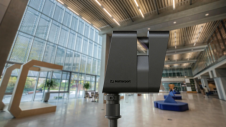
Due to the high accuracy demands, static laser scanning was chosen for 3D data acquisition instead of kinematic laser scanning systems. In order to ensure rapid data acquisition, four identical static laser scanners were used, namely the Zoller + Fröhlich IMAGER 5010 X series. Deviations of individual calibrations are a critical issue when using several systems in one project. Hence, all systems were regularly checked using a plane-based calibration routine (Rietdorf et al. 2004) that assesses the quality of the configuration of the scanner’s axes.
The initial status of the building was captured before any renovation measures were undertaken. This involved six weeks of scanning and establishing the tacheometric network. In close coordination with the clinic management, scans were captured primarily during the day by four survey crews in parallel. A total of 12,932 laser scans were captured, comprising a raw data volume of 540GB (*.zfs format). A key challenge in projects of this size is how to organize all the scans. In this case, a naming convention was applied based on the 14 architectonical entities of the building.
Data security
According to German law, just as in many other countries, healthcare institutions fall under the category of critical infrastructure. Hence, to avoid the risk of prosecution, data security was a key factor in this project; cloud-based or external data-processing and data-storage solutions were strictly forbidden. Instead, all computations had to be performed on local computers, and the data was stored on a protected in-house server.
Point cloud registration
The vendor-neutral software Scantra 3.0 was used to register the approximately 13,000 scans. Since Zoller + Fröhlich grants third-party developers direct access to its proprietary file format *.zfs, there was no need to convert the original scans prior to processing. This saved considerable time and disk space. The chosen software follows a sequential data substitution process that supports projects of this size (Wujanz et al. 2018). In general, the following procedure was deployed:
- Data import of static laser scans including inclinometer readings and ground control points
- Detection of planes and local targets
- Pairwise registration between scan pairs and point matching
- Network adjustment/quality assurance
- Export of the registered point clouds
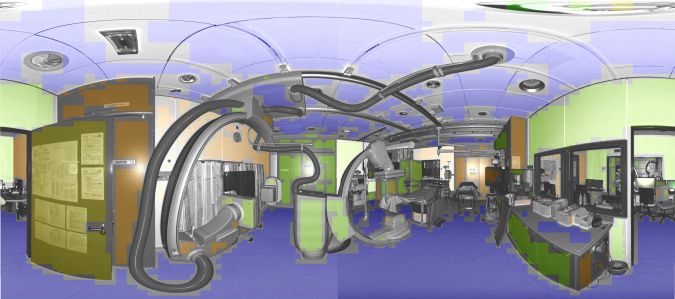
In this project, pairwise registrations were computed based on identical planes between scan pairs. Figure 1 illustrates detected planes within a single scan that substitute the original point cloud and hence drastically reduces the memory requirement. Apart from plane parameters, every plane receives covariances that serve as weights during pairwise registration.
Network optimization
In practice, a common method is to break up a project into individual clusters that are linked together by ground control points. A notable disadvantage of this ‘Frankensteinian’ course of action is that transition areas are inevitable between individual groups. In order to avoid this, all scans were optimized in one common adjustment. Key in this enormously ambitious task was the aforementioned data substitution strategy.
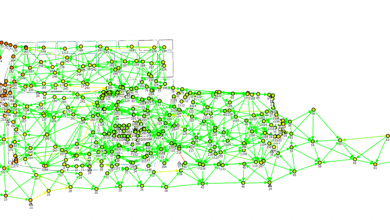
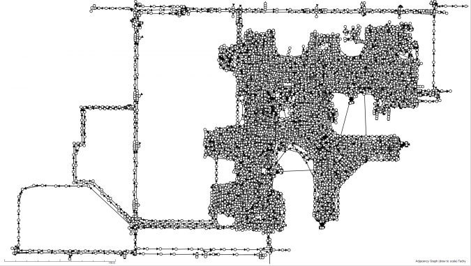
The data volume of the entire project was narrowed down from 540GB of raw data volume to 4.6GB of geometric information and 10.4GB of visual information in the form of images for every scan. Only geometric information is required for the block adjustment, which minimizes discrepancies between pairwise registrations, inclinometer readings and ground control points. Optimizing the final network with 24,706 pairwise registrations and 408 point identities to ground control points required just over three minutes on an ordinary Dell laptop with 64GB RAM and 2.3GHz with eight processors. A maximum of 1.4GB RAM had to be provided by the computer. Figure 2 illustrates a bird’s-eye view of the network graph.
Quality assurance & deliverables
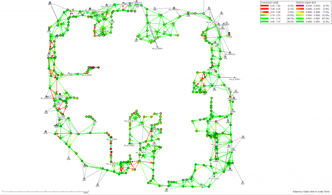
A typical measure to verify the quality of a network in the 3D mapping community is to provide residuals (or statistics thereof) to ground control points. Since these measures can be easily manipulated in one’s favour (Wujanz 2022), individual geodetic quality measures were provided for every single scan based on error propagation. These metrics are also referred to as ‘stationing error’ and quantify how much a single scan is statistically ‘shacking’ with respect to ground control points. Note that these measures vary considerably depending on the given survey configuration. Figure 3 illustrates such variations in a complex exterior part of the project that consists of 338 scans. It can clearly be seen that the vast majority of stations are positioned in the range of 2.5 to 4.9mm (1σ), yet this notably drops off in some parts. This can be explained by the façade, which mostly features glass elements and which was heavily vegetated in some parts with very limited views for tacheometry.
The identification of errors is a time-consuming process in laser scanning. Hence, a procedure was applied that identified outliers based on the outcome of network adjustments. This produced a shortlist of statistically suspicious observations. As a result, only a few observations needed to be inspected rather than all of them, which saved a substantial amount of time. Registration of this huge dataset required three weeks in total. After the final quality assurance was completed, the registered scans were voxelized and filtered by range in order to minimize the data volume for the client. The resulting *.E57 files occupied 2.3TB of memory. Besides the point cloud itself, the client also received a network overview which helps to identify scans that are required in the planning process.
Conclusion
This article outlines a 3D mapping project of a large-area clinic that was captured by static laser scanning. The resulting digital twin will serve as a basis for BIM-based planning during the 17-year renovation period and had to satisfy LOA30. Challenges during this project included the size and complex architecture of the building, which resulted in a large static laser scanning network. As a consequence, a huge dataset consisting of nearly 13,000 scans had to be processed by means of plane-based registration and a network adjustment. After registration, the project point cloud was exported and submitted to the client in form of *.E57 files.
Further reading
Rietdorf, A., Gielsdorf, F., & Gruendig, L. (2004). A concept for the calibration of terrestrial laser scanners. In Proceedings of INGEO 2004 and FIG Regional Central and Eastern European Conference of Engineering Surveying. Bratislava, Slovakia (Vol. 11, p.13).
Wujanz, D., Schaller, S., Gielsdorf, F., & Gründig, L. (2018). Plane-based registration of several thousand laser scans on standard hardware. International Archives of the Photogrammetry, Remote Sensing & Spatial Information Sciences, 42(2).
Wujanz, D. (2022). Taming errors... pt. 10: What residuals to geodetic control points ARE NOT telling you…. https://www.linkedin.com/pulse/taming-errors-pt-10-what-residuals-geodetic-control-points-wujanz/ (Accessed: 05.09.2022)

Value staying current with geomatics?
Stay on the map with our expertly curated newsletters.
We provide educational insights, industry updates, and inspiring stories to help you learn, grow, and reach your full potential in your field. Don't miss out - subscribe today and ensure you're always informed, educated, and inspired.
Choose your newsletter(s)