Geodetic control networks: challenges and solutions
Essential tools for deformation and environmental monitoring
What are the key challenges in establishing precise geodetic control networks? This is one of the most important tasks of geodesists and land surveyors, since geodetic control networks are essential for the deformation and environmental monitoring of dams, tunnels, high towers, landslides and bridges, among others. This article discusses the main challenges relating to vertical angles and provides some recommendations for how they can be overcome.
The key challenges when establishing precise geodetic control networks relate to the vertical angles that are employed to reduce the collected slope distances to horizontal distances. This approach, called ‘trigonometric slope distance reduction’, is well known and commonly practised in geodesy. However, reducing slope distances to horizontal distances should be done without existing systematic errors.
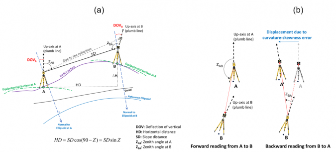
Collecting vertical angles (or zenith angles) using a total station creates various issues. Refraction error, geometric effect (due to curvature-skewness of Earth’s reference model) and physical effects (due to the deflection of verticals) are the main challenges that affect the collected vertical angles (Figure 1). These effects show that the vertical angle is a sensitive observation.
Effects on the vertical angle
Refraction error occurs because of atmospheric density variation along the baseline. The air temperature gradient in the direction perpendicular to the line of sight is the main factor in modeling the refraction effect. As shown in Figure 1, geometric and physical problems occur because of the non-parallelism of the up-axes at the start and endpoint of the baselines in the geodetic control networks. The geometric problem is related to the Earth’s reference shape (spherical or ellipsoidal model). Due to the curvature problem, the up-axes will not be parallel. However, by selecting an ellipsoidal model for the Earth, an additional problem will appear that is called the skewness problem (i.e. the up-axes at points A and B will not be in the same normal sections/mathematical sight of view). The results show that the geometric error (the non-parallelism of the up-axes) can reach to 32 arc-seconds for 1km baseline length with 100m height difference, where the corresponding slope distance reduction is 8mm. The physical problem (or the deflection of verticals problem) is due to the separation of the normal line to the Earth’s reference ellipsoid and plumb line. The problem is that the observations are collected on the Earth’s surface (physical shape of the Earth), but the Earth’s mathematical shape (e.g. reference ellipsoid) is used for calculations. Therefore, observations should be corrected to the normal to the ellipsoid as a reference.
It is important to mention that it does not matter which type of coordinate system is defined in establishing a classical geodetic network (local geodetic or local astronomic coordinate system). The deflection of vertical problem can reach to 16.5mm (for 70° zenith angle) and 4.2mm (for 85° zenith angle), assuming 1km baseline length. Geometric and physical effects will directly influence the zenith angles and, consequently, the reduction of the slope distances will be affected. Since these problems have not been clearly mentioned in the guidelines, the quantification of these problems in Bagherbandi et al. (2022) can be useful for future guideline compilation.
Solutions to the challenges
In the existing guidelines, the recommended solution to the above-mentioned problems is the reciprocal reading of vertical angles. However, to remove the refraction error, the vertical angle should be collected simultaneously from both ends of a distance (see e.g. Engineer Manual 2018, Section 3-4). The reciprocal reading can be a solution for geometric and physical effects if the points are at the same elevation. Otherwise, both geometric and physical errors should be considered for correcting vertical angles.
Cost and time are both important factors in establishing optimum and precise geodetic networks and should always be considered. Collecting reciprocal observations is time-consuming, especially in areas of rough topography (e.g. dam sites), and increases the fieldwork and project costs. In addition, it is not always possible to follow the guidelines and design the geodetic control network with the points at the same elevation because of the project circumstances (e.g. existing rough topography and monitoring high towers). The authors’ results show that disregarding geometric and physical effects can lead to signifcant errors, especially if there are large height differences between the points (even if the vertical angles are collected reciprocally).
Up until now, textbooks and geodetic lecture notes have only presented the geometric effect on the horizontal angles. But how can this error be formulated and quantified for the vertical angle? The physical problem can be corrected using a regional gravity database and calculating the precise deflection of vertical components. Detailed information about this problem and its solution can be found in Bagherbandi et al. (2022) and Heiskanen and Moritz (1967, p. 312).
How to avoid reading vertical angles
Two methods can help land surveyors to eliminate collection of the vertical angle using only the unidirectional slope distances and horizontal angles: 3D network adjustment (cf. Ghilani 2017, Chapter 23), and a recently proposed method by Shirazian et al. (2021) called the network-aided method. In the network-aided method, one can use only unidirectional slope distances in the form of a 3D free network adjustment in the first step. The horizontal distances are calculated in the next step using adjusted coordinates (Easting and Northing components). Lastly, the calculated horizontal distances, along with the horizontal angles or direction observations, are used in the final network adjustment to calculate the 2D geodetic network.
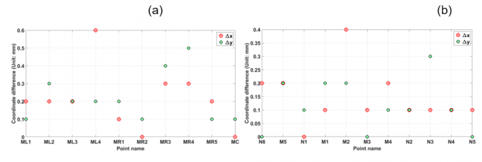
The authors evaluated the network-aided method using two geodetic networks in Iran (Mojen Dam and Damghan Dam). Figure 2 shows the coordinate differences obtained by using reciprocal and unidirectional observations (i.e. network-aided method and using only slope distances and horizontal angles). The results illustrate that the discrepancies between the results of the two methods are less than 1mm and are therefore neglible. In addition, the network-aided method results in similar error ellipses (or, in some points, smaller semi-major and semi-minor axes) and better redundancy numbers.
Advantages of network-aided method
The network-aided method has some advantages compared to 3D network adjustment. Comparing the two methods shows that the number of degrees of freedom in the network-aided method will be larger than in 3D network adjustment. This means that the average redundancy (or relative redundancy), which is an important network quality factor (especially when designing networks), is higher in the proposed method by the authors, as validated by testing in two dam deformation monitoring networks.
Further reading
Bagherbandi, M., Shirazian, M., Ågren, J., & Horemuz, M. 2022. Physical and geometric effects on the classical geodetic observations in small-scale control networks. Journal of Surveying Engineering. https://doi.org/10.1061/(ASCE)SU.1943-5428.0000407.
Engineer Manual. 2018. Structural deformation surveying. EM1110-2-1009. Washington, DC: USACE.
Ghilani, C. D. 2017. Adjustment computations: spatial data analysis. John Wiley & Sons.
Heiskanen, W. A., & Moritz, H. 1967. Physical Geodesy. WH Freeman and Company. San Francisco, CA.
Shirazian, M., Bagherbandi, M., & Karimi, H. 2021. Network-Aided Reduction of Slope Distances in Small-Scale Geodetic Control Networks, Journal of Surveying Engineering. 147(1983), 1-10. https://doi.org/10.1061/(ASCE)SU.1943-5428.0000375.

Value staying current with geomatics?
Stay on the map with our expertly curated newsletters.
We provide educational insights, industry updates, and inspiring stories to help you learn, grow, and reach your full potential in your field. Don't miss out - subscribe today and ensure you're always informed, educated, and inspired.
Choose your newsletter(s)


