Lidar Flight Planning
A System with Minimal User Intervention
Airborne Lidar has become a regular technology for acquiring accurate, consistent and dense point clouds. However, the constraints on specifications, available sensors and aerial platforms are still a challenge for Lidar data acquisition. Optimal flight planning is essential. Current practices rely on rules of thumb and trial and error, meaning that optimal solutions are rare. The authors have developed a Lidar flight planning system which does provide an optimal solution at a high level of automation and requiring minimal user intervention.
Once acquired, Lidar data should satisfy the specifications on density, overlap, spatial distribution and accuracy. Data clusters and voids should be absent. Further requirements can be found in U.S. Geological Survey National Geospatial Program Lidar Guidelines and Base Specification Version 13. The constraints on specifications, available sensors and aerial platforms make Lidar data acquisition a challenging task. The need to simultaneously capture photogrammetric imagery further complicates matters.
Flight planning
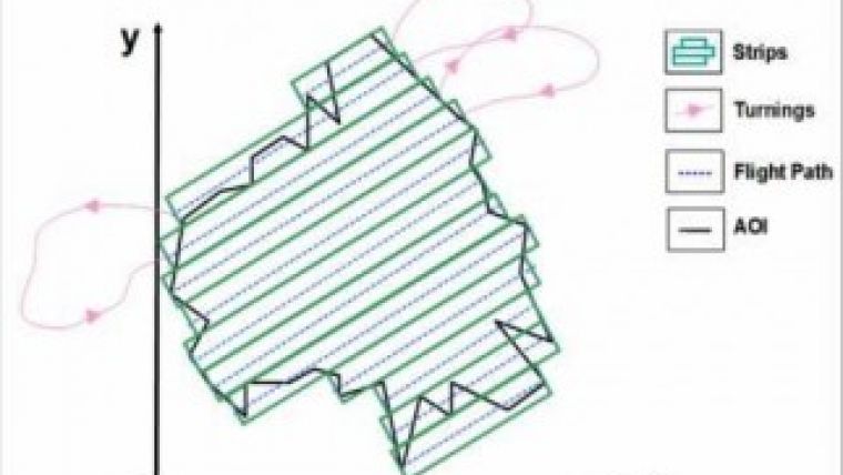
Lidar flight planning starts with dividing an area into rectangular strips (Figure 1). After finalising one flight line, the aircraft has to turn to the next flight line. Flight planning defines flight lines and other flight parameters through a simulation exercise, thus enabling Lidar and/or image data of predefined specifications to be acquired at minimum costs. Flight planning explores the relationships between the Lidar scanner, camera, aircraft, navigation sensors (GNSS and IMU), terrain features and other components. The resulting flight plan is used by the flying crew and sensor operator.
Flight planning should thus take into account the possible operation ranges of sensors including pulse repetition frequency (PRF), field of view (FOV), scan frequency, beam divergence, ground sampling distance (GSD), flying height, trajectory position and attitude. Furthermore, it should account for the accuracy of the resulting 3D coordinates of the points in the point cloud or of the 2D coordinates measurable in the orthoimagery as the consequence of observation errors. Flight planning should also consider preferences in direction of flight, type of turning, maximum banking angle and cushion period (the time needed in addition to the time to fly from the end of one strip to the beginning of the next strip).
Current practice
All of the above should be included in a single, comprehensive software system to yield the optimal flight plan. However, current practices consist of manual and semi-automatic approaches; both use rules of thumb, such as that the flying direction should be along the longest direction. The relationships between parameters are realised computationally by varying one parameter and noticing its effect, both on the others and on the flight plan itself. These approaches are iterative, based on trial and error, treat all parameters as separate entities and make a decision through heuristic rules or user intervention. These semi-automatic approaches are implemented as graphical user interface-based (GUI-based) software. A patented application by Murphy (2004) is an example of such software. Recently, Landtwing and Whitcare (2008) and Tian et al. (2011) published preliminary studies in which they highlighted the limitations of the current approaches and the need for improvement.
New system
Therefore, the authors conducted a comprehensive study aimed at developing a software package which accounts for all components of airborne Lidar data acquisition – such as sensor, platform, user requirements, user preferences and terrain features – and photogrammetric image acquisition during the same flight. The resulting system primarily exploits mathematical relationships between the various components. For example, the relationships between data density, overlap and terrain relief are expressed as mathematical formulas. The same is true for the relationships between the along-track and across-track spacing and nominal pulse spacing. In case of simultaneous image acquisition, the relationship between the FOV of the onboard digital camera and FOV of the Lidar scanner has to be exploited. The development of the mathematics departs from scrutinising the basic principles. Next, the formulas are converted into algorithms and finally into computer code. The system also evaluates the various turning mechanisms, because the type of turning affects the optimal design. A distinction is made between consecutive, non-consecutive and hybrid turnings. Consecutive turning means that the next strip is adjacent to the previous one; this is in contrast to non-consecutive turning. A combination of the two is called hybrid turning. Unlike previous approaches, the determination of the optimal turning mechanism is an integrated part of the system. The accuracy of the six exterior orientation parameters obtained from the GNSS/IMU device, the accuracy of the Lidar scanner and the accuracy of the spatial arrangement of both devices propagate as errors in the final products. The required accuracies of the end products are also taken into account to determine the optimal flight path.
Objective function
The mathematical relationships reveal that the flight duration, data requirements and the quality of data are functions of the scanner parameters (PRF, FOV, scan frequency) and flying parameters (flying height, flying speed, flying direction). An objective function has been developed to relate flight duration to these parameters while simultaneously accounting for the constraints of the data specifications and quality, among others. The nature of the parameters in this objective function, the objective function itself and the constraints revealed that genetic algorithms (GA) provide good solutions for optimising the objective function. GA offers a range of configurations for solving a problem, and an algorithm has been found that solves the complex cases of airborne Lidar the best.
Example
The black lines in Figure 2 show the boundary of a 4km2 area of interest (AOI). The AOI has to be captured by Lidar and digital images simultaneously. Table 1 lists the data requirements and specifies sensors and aircraft. The ratio of the difference between along-track and across-track spacing to along-track spacing may be a maximum of 10%.
|
Data densities: minimum / maximum |
10 / 13 points/m2 |
|
Minimum overlap / endlap / sidelap |
10% / 60% / 25% |
|
Altimetric / planimetric errors |
10cm / 15cm |
|
Maximum GSD |
15cm |
|
Relief variation across AOI |
200m |
|
Maximum bank angle / cushion period |
25º / 30 seconds |
|
Lidar scanner |
Optech’s ALTM 3100EA |
|
Camera |
Applanix DSS 322 (60mm focal length) |
|
Navigation sensor |
Applanix POS AV510 |
|
Aircraft |
Cessna |
Table 1, Data requirements and device specifications.
The above requirements and specifications were input into the flight planning software resulting in the strips as shown in Figure 2 and scanner and flying parameters as listed in Table 2.
|
Scanner Parameters |
Flying Parameters |
||||
|
FOV |
Scanning frequency |
PRF |
Height |
Speed |
Direction |
|
7º |
70Hz |
100KHz |
886.3m |
45.9m/s (90 knots) |
9.9º |
Table 2, Optimal values of scanner and flying parameters.
Concluding remarks
This approach requires minimum user intervention and automatically calculates the optimal flight plan with the shortest flight duration, while simultaneously meeting the data requirements and ensuring quality for any type of terrain. The flight planning system is versatile and expandable for new definitions of flight duration, field limitations, future needs and any additional requirements of the Lidar data. Compared to current practices, it provides a significantly higher level of automation. A patent has been filed by the authors at IIT Kanpur.
Biographies of the authors
Ajay Dashora has an educational background in remote sensing and received a PhD degree from the Indian Institute of Technology Kanpur (IITK) in India for his study of airborne Lidar. He is the principle innovator of the filed patent. His research interests are in physical modelling and integration of remote sensing techniques.
Email: ajaydashora@gmail.com
Bharat Lohani is associate professor in the Department of Civil Engineering at the Indian Institute of Technology Kanpur (IITK) in India. There, he leads the Lidar research group and has been a key person in the award-winning Lidar Simulator. Dr Lohani is currently co-chair of ISPRS WG V-2 and a Fellow with the Institution of Surveyors, India.
Email: blohani@iitk.ac.in
Kalyanmoy Deb is professor in the Department of Mechanical Engineering at the Indian Institute of Technology Kanpur (IITK) in India and founder of Kanpur Genetic Algorithms Laboratory (KANGAL). He is spearheading all research activities in the field of optimisation at KANGAL and has received many accolades and prestigious national and international awards in the field of optimisation research.
Email: deb@iitk.ac.in

Value staying current with geomatics?
Stay on the map with our expertly curated newsletters.
We provide educational insights, industry updates, and inspiring stories to help you learn, grow, and reach your full potential in your field. Don't miss out - subscribe today and ensure you're always informed, educated, and inspired.
Choose your newsletter(s)


