Mapping with Mobile Lidar
High Speed, Accuracy and Density
The use of Mobile Lidar systems enters the scene when large areas have to be surveyed at accuracy and resolution exceeding those available through aerial photogrammetry, and when using static Lidar is impractical. The Lynx Mobile Mapper captures high-accuracy, high-density points, allowing easy and precise identification of objects.
In 2006 Sineco S.p.A, an Italian engineering firm belonging to the ASTM Group, began collaborating with Optech Incorporated, the Canadian manufacturer of laser-based imaging systems, to develop a mobile Lidar system. The first prototype, ready in early 2007, combined two ILRIS-3D laser scanners with a position-and-orientation system (Applanix POS LV 420). This proof-of-concept paved the way for development of the new LYNX Mobile Mapper, a fully integrated system operating at speeds up to 100km/hr.
Going Mobile
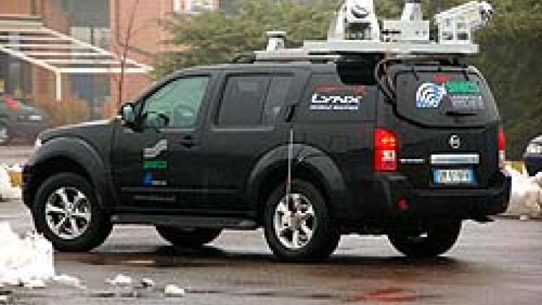
Two orientated Lidar sensors, the IMU and GPS antennae are mounted on top of a vehicle (Figure 1); rigid mounting ensuring alignment and accuracy are preserved between sensors, IMU and GPS antennae. Since orientation and position of the two Lidar sensors with respect to the Applanix POS system must be precisely known, calibration must be carried out on the Lidar sensors after mounting on the vehicle. The system accuracy is better than 5cm, measurement rate is 100,000 points per second per sensor, and resolution is up to 1cm. The field-of-view is 360°; that is, the two Lidar sensors scan the entire area and minimise shadowing caused by roadside objects (Figure 2).
Geo-Reference
IMU and GPS are critical for any mobile system, as they are necessary for geo-referencing the data. However, for ground-based mobile systems IMU and GPS alone are insufficient, since trees, buildings and overpass create periods in which GPS signals may be blocked. Auxiliary sensors and advanced processing are needed during GPS outages, and these are part of the Applanix POS/LV 420.
This position-and-orientation system, which enables automatic geo-referencing of a point, includes a Distance Measurement Instrument (DMI) in addition to accurate IMU and two GPS antennae.
Heading Calculation
The second GPS antenna can be used to aid heading calculation in areas of high latitude. The DMI is a wheel-mounted rotary shaft encoder that measures linear distance travelled and helps the POS LV to constrain drift errors during GPS outages. This helps when the quality of received GPS signals is poor. When the vehicle stops the DMI provides Zero Velocity Updates. Most critical is that all navigation data generated by the two GPS receivers, IMU and DMI, are ‘tightly coupled processed'; that is, simultaneously processed in an integrated manner. The Lidar sensors and POS are linked via their clocks, which should therefore be carefully synchronised.
Highway Survey
New work was planned on the highway connecting Korinthos to Athens in Greece, including construction of a new link-up motorway and the preservation of existing parts. In March 2008 60km of this highway was surveyed to create an accurate 3D CAD reconstruction of the main features, including pavement, structures, slopes and road signs (Figure 3). Both carriageways of the highway were surveyed in three hours at an average speed of 50 km/hr. Compare this to the 120 working days needed in 2007 to scan 80km of highway using static laser-scanners and a total station . The point-cloud, consisting of 980 million points, was converted from WGS84/UTM34 to the Greek reference system, CGR87, with a final average spot spacing of 11cm. To increase accuracy, six base-stations and ground-control points were positioned every 50 to 80 metres along the corridor. Final point-cloud accuracy is within 2cm. Both PolyWorks and Pointools were used for data processing.
City Modelling
In January 2008 the historic area of Leicester in England was surveyed to obtain a reconstruction of some of the main buildings for digital archiving. The narrow streets and tall buildings regularly caused GPS outage, but the DMI made it possible to compensate for non-availability of GPS data. Traffic congestion limited vehicle speed to 30 km/hr. In twenty minutes five blocks were surveyed and 144 million points generated, with spot spacing of 4cm. One GPS base-station placed in the neighbourhood was used. The processing was done with Pointools (Figure 4).
Further Facilities
The software needed to create 3D-models from the point-clouds requires more facilities to reduce human effort. We are now working on automatic routines for feature extraction and collection, automatic cross-section creation and data segmentation.
Acknowledgements
Thanks are due to Michael Xinogalos, Astrolabe Engineering firm, and Faraz Ravi.

Value staying current with geomatics?
Stay on the map with our expertly curated newsletters.
We provide educational insights, industry updates, and inspiring stories to help you learn, grow, and reach your full potential in your field. Don't miss out - subscribe today and ensure you're always informed, educated, and inspired.
Choose your newsletter(s)


