Medium-format Cameras for High-accuracy Mapping
Field Test of the Phase One iXU-RS1000 Camera
Small and medium-format cameras are increasingly gaining popularity for mapping small and medium-size areas, corridors, construction sites and cities. They are also used as companions of Lidar systems, mounted on unmanned aerial systems (UASs), and for monitoring and inspecting infrastructure. The author of this article investigated the suitability of the Phase One iXU-RS1000 camera for high-accuracy mapping and found this medium-format camera to be a metric camera with stable and clearly definable interior orientation parameters, producing images of high geometric and radiometric quality.
In photogrammetry it is important that cameras produce images of which the geometric distortions are as small as possible or in compliance with known distortion models, while the focal length of the lenses and the principal point remain stable over time. The photogrammetric accuracy assessment of the Phase One iXU-RS1000, a medium-format camera, was carried out to test its suitability for high-accuracy mapping and was done by a field test. The test included a flight over a test field, image matching and aerial triangulation (AT), camera calibration based on AT, and analysis of the accuracy of stereoscopic measurements.
Medium Format
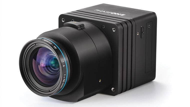
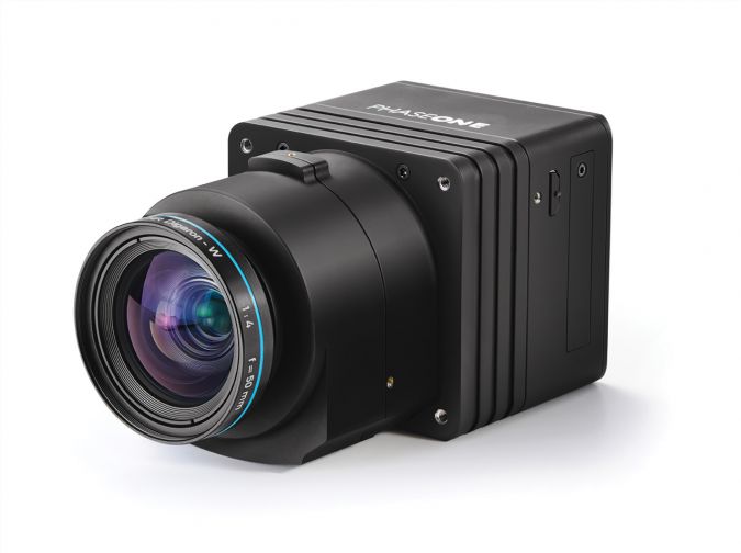
The iXU-RS1000 series consists of 100Mpx cameras with a pixel size of 4.6µm, an image capture rate of 0.6 seconds per frame and an exposure time of up to 1/2,500 seconds. The cameras can be equipped with lenses with five different focal lengths: 50mm, 70mm, 90mm, 110mm and 150mm. The camera size (10x10x20cm including lenses) and its weight of less than 2kg (see Figure 1) allow easy installation in small and lightweight aircraft, gyrocopters or medium-size UASs. The small dimensions and lightweight characteristics significantly reduce the operational costs of mapping projects.
Test Flight
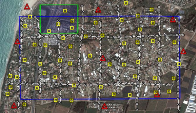
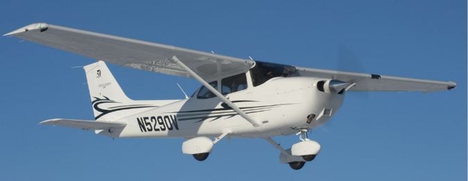
The test site, situated in the vicinity of the village of Kfar-Vitkin in Israel, covered 1.2km from north to south and 2km from east to west (Figure 2). Manmade features and manholes were chosen as signalised ground control points (GCPs). All 53 GCPs were located on the ground and were measured according to the static GNSS survey procedure with one reference station. The coordinates of this base station were measured during two independent one-hour sessions. Each GCP was measured by two independent half-hour sessions resulting in an absolute planar accuracy (X,Y) of 0.8cm root mean square (RMS) and an RMS of 1.3cm in height (Z). The camera used in the test had a focal length of 90mm and was installed at the rear of a Cessna 172 aircraft (Figure 3). The aerial survey parameters are listed in Table 1.
|
Flight altitude (above ground) |
2,500 feet / 760m |
|
GSD |
4cm |
|
Distance between flight lines |
230m |
|
Side overlap |
49% |
|
Forward overlap |
80% |
|
Frame size |
450m x 340m |
|
Orthophoto angle |
17° |
|
Building lean |
15% |
|
Ground speed |
100 knots |
|
Strips |
SN – 9; WE – 2 |
Table 1: Aerial survey parameters.
The testing procedure included flight planning and execution, image matching for determination of tie points and aerial triangulation (AT), camera calibration based on AT, analysis of AT accuracy using different GCP and checkpoint (CP) configurations, and stereoscopic measurements of GCPs and CPs. Agisoft Photoscan Professional was used for image matching and for GCP and CP measurements. Bingo was used for bundle block adjustment, camera calibration and accuracy assessment. AtlasKLT was used for stereoscopic measurements of GCPs and CPs.
Camera Calibration
Self-calibration is aimed at the accurate calculation of focal length and principal point of the camera. These interior orientation parameters are calculated from a simultaneous bundle adjustment of all images of the block using tie points and GCPs. The accuracy depends on the number and size of image overlaps, number of tie points and GCPs and their accuracy, and other factors. A total of 202 images were used with an average of 222 tie points per image. All 53 GCPs were used. The adjustment resulted in a high photogrammetric overall accuracy of 1.84µm (0.4 pixel). The RMS error of tie points was 1.7µm in the image plane (0.3 pixel). The RMS of tie points on the ground was 0.8cm in planar position (0.2 pixel on the ground) and 3.8cm in height (0.8 pixel on the ground).
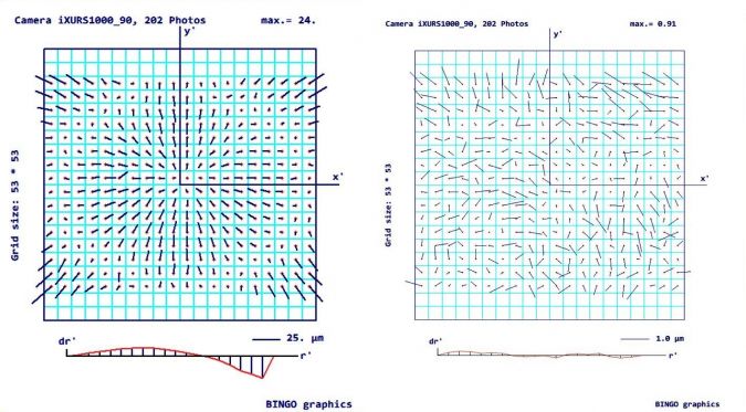
During the self-calibration the lens distortion was also calculated. Figure 4 clearly shows symmetrical radial distortion with a maximum of 24µm before the image was fixed. After fixing with additional parameters describing a simple symmetrical radial distortion, the maximum distortion decreased to 0.91µm, which is just 0.2 pixel. The distortion model of the iXU-RS1000 with a focal length of 90mm fully corresponds to a standard Brown-Conrady distortion model. By applying radial corrections, the maximum distortion is reduced to less than 1µm.
Accuracy
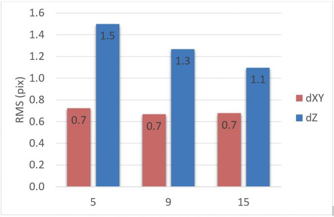
The accuracy of the block was determined using three GCP and CP configurations: 5 GCPs and 48 CPs, 9 GCPs and 44 CPs, 15 GCPs and 38 CPs (Figure 5). The planimetric accuracy always lies at around 0.7 pixel, regardless of configuration. Height accuracy ranges from 6cm (1.5 pixel) with 5 GCPs to 4.4cm (1.1 pixel) with 15 GCPs. This high accuracy can be made even better by improving the accuracy of GNSS data.
To determine the accuracy of the stereoscopic measurements and the presence of vertical parallax residuals after relative orientation, 53 GCPs were measured on 91 stereo pairs with 60% forward overlap. On each stereo pair the points were measured twice. To eliminate effects of possible block deformations on stereoscopic measurements, exterior orientation parameters were calculated from bundle block adjustment with the use of all 53 GCPs.
It can be calculated that the theoretical planimetric accuracy will be 0.5 pixel (2cm) and the theoretical height accuracy will be 2.8 pixels (11.2cm) for a camera with a focal length of 90mm and forward overlap of 60%. The test obtained a planar accuracy in terms of RMS of 0.8 pixel (3.14cm) and a height accuracy of 1.72 pixel (6.87cm). The planimetric and height accuracy obtained in the test were affected by the accuracy of the GCPs, of which the planar RMSE was 0.8cm and the height RMSE was 1.3cm. When these effects are taken into account, the planimetric accuracy of stereoscopic measurements corresponds to the theoretical accuracy, and the height accuracy obtained in the test is even better than the theoretical value.

Value staying current with geomatics?
Stay on the map with our expertly curated newsletters.
We provide educational insights, industry updates, and inspiring stories to help you learn, grow, and reach your full potential in your field. Don't miss out - subscribe today and ensure you're always informed, educated, and inspired.
Choose your newsletter(s)


