Night-time mobile mapping of road surface luminance
Capturing road environment lighting inventories using a luminance-calibrated mobile mapping system
A new measurement system is being developed to evaluate night-time road lighting and safety conditions based on luminance-calibrated 3D point cloud data. This new approach integrates imaging photometry, which is commonly used to measure road lighting, with mobile laser scanning techniques, which are mainly used to measure the 3D geometry of the road environment. There are many interesting potential applications of the resulting georeferenced luminance point cloud.
In road traffic, the role of illumination is to improve the visibility of the road and the surrounding environment. Illumination is also one of the most effective ways of increasing road safety; it has been shown to reduce the number of accidents in road traffic by 30%. Road and street lighting also promotes the implementation of an unimpeded environment. However, the hazardous effects of light include disturbing, external light shining into an illuminated area which causes discomfort and interferes with the visibility of essential information.
Trends in road lighting solutions
LED-based illumination technology has become widespread over the past few years because of its energy efficiency, even light quality, excellent colour reproduction and long life. The energy consumption from road illumination can be reduced significantly by switching to LED luminaires. Another trend in lighting solutions for road and street environments is the intelligent lighting system. Intelligent road lighting will automatically optimize the illumination conditions, taking into account the prevailing road and traffic situation, the properties of the road surface and the luminous flux of the lamps. A new, feasible method for road-illumination data gathering and presentation could possibly accelerate and proliferate the advantages of novel road lighting technology.
Illumination conditions in street and road environments are defined using a luminance value (cd/m²). Commonly used parameters are the maintained average luminance over the whole driving lane, the uniformity ratio on the driving lane and the longitudinal uniformity ratio. The traditional measurement approaches for illumination conditions in road and street environments are point measurements of luminance as well as imaging luminance measurements taken on site. Planning instructions for road illumination do not actually stipulate the measurement approach, but just the number of measurement points and their locations as well as the location of the observer. Of these measurement approaches, point luminance measurement is only suitable for small-scale use as it is too slow to measure extensive road environments. Most road environment luminance measurements are made using an imaging luminance meter. In practice, an imaging luminance meter is a digital camera that has been calibrated so that the RGB values it records can be interpreted as luminance values.
The author outlines methods for 3D measurement and modelling of road surface luminance using mobile laser scanning and luminance imaging (Figure 1). In addition, an example is presented in which the mobile measurement of 3D luminance is used for assessing the light-obstructing effect of roadside vegetation, and they compare this to the conventional 2D method.
Luminance calibration
Digital cameras have been used for luminance measurements for around two decades. The use of digital photography for taking illumination measurements in a road environment requires that the pixel values of the raw pictures are calibrated against a known luminance source. Colouring a 3D point cloud in luminance pictures further requires the calibration of the camera’s internal geometry, and corrections need to be made to the pictures’ lens distortions. In luminance calibration it is essential that the same settings are used in the calibration as in the imaging in the field. In practice, calibrations are done in a dark room with a known standard luminance source which is regulated to correspond to the luminance levels of an illuminated road surface. In this way, the picture’s RGB values in relation to the luminance values can be resolved. For the mobile imaging in this study, a Ladybug 3 panorama camera of the Trimble MX2 MMS was calibrated.
Combining luminance images with mobile laser scans
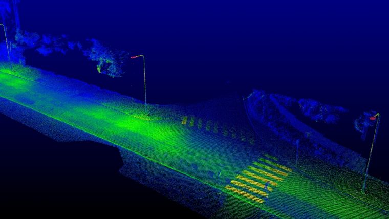
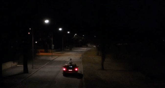
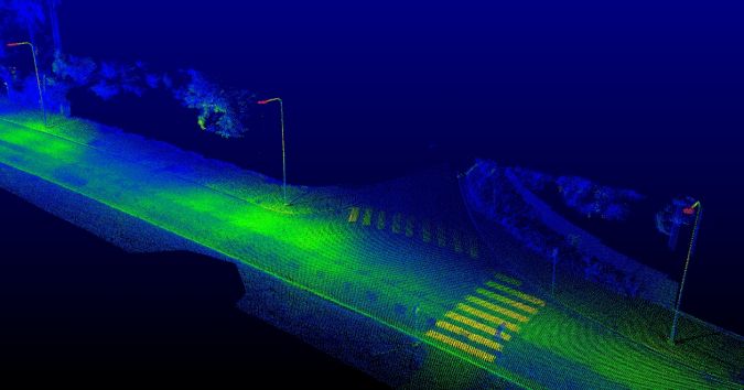
Combining luminance images with mobile laser scans was tested at Munkkiniemenranta in Helsinki, Finland, where the experiments were carried out in night-time illumination on a two-lane stretch of road which was one kilometre in length (Figure 2). The material was measured using a Trimble MX2 mobile mapping system. The equipment consisted of a panorama camera (Ladybug 3), two laser scanners (SLM 250) and a positioning system (Trimble AP20 GNSS-inertial system). The stretch of road was mapped in both directions and the data was collected over a period of about 10 minutes. The equipment preparation and initialization of the positioning system, taking into account the measurement site, took about 30 minutes. The laser scanning material of the site consisted of about 40 million point observations. The panorama camera was set up to take images at two-second intervals.
In the post-processing of the material, the mapping system’s location data and the measurement route were calculated using the Applanix POSPac MMS software to create a VRS base station network around the measurement area. The measurements produced by the laser scanning were combined with the location data in the Trimble Trident software, where the measurement observations were also combined with the RGB values from the images taken with the panorama camera. The luminance calibration of the panorama camera enabled a final luminance value to be calculated for each measurement point.
The whole measured road environment was segmented into areas of analysis which were similar to the measurement areas in the road lighting design recommendations. One area of analysis encompassed a one-lane-wide area between two adjacent road luminaires longitudinally. In order to calculate the longitudinal uniformity, a 20cm wide longitudinal strip of the point cloud was considered as the centre line of the lane. In digital image processing, it is common to reduce noise using a median averaging filter. Hence, median filtering was used to reduce noise from the luminance values of the point cloud. The filtering was executed on the XY plane on the road surface for each point with a radius of 50cm.
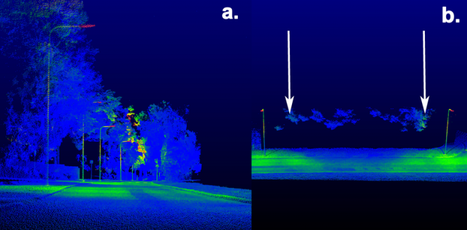
One possible application for 3D mobile luminance measurement is assessing the light-obscuring effect of roadside vegetation. Figure 3 shows the road environment luminance with a view similar to conventional 2D imaging and a possible view using a 3D luminance point cloud. The difference is obvious. In 2D, the decrease in the road surface luminance can be observed, but the presentation is very limited. In 3D, even a branch that needs to be pruned can be identified, and the road surface can be viewed in a more comprehensive manner.
Conclusions
In this study, imaging luminance photometry was integrated in a mobile laser scanning system, which made it possible to produce 3D luminance point clouds of street and road environments in night-time illumination. The camera settings were adjusted to take images at low illumination levels so the material could be used especially for defining road surface luminance values. In terms of luminance dynamics and measurement accuracy, the measurement results are slightly limited compared to conventional stationary luminance imaging. Evident benefits of the developed system include registering the luminance information into dimensionally accurate and georeferenced 3D models, and a mobile method of measurement which enables the measurement of large traffic areas rapidly.
The 3D measurement and modelling of street and road illumination will improve opportunities to assess the reflection of road lighting from the road surface, distinguish disturbing light coming into the environment, identify places which are in shadow, assess visibility conditions and compare the capabilities of different lighting systems to illuminate a road environment. In addition, laser scanning methods enable detailed modelling of the road environment so the material can be used to automatically identify road markings, curbs, posts, traffic signs and signals. Furthermore, nimble assessment and monitoring of the light-obstructing effect caused by roadside vegetation is possible utilizing combined luminance imaging and mobile 3D measurements. The author considers this method potentially suitable for other lighting measurement purposes such as in tunnels, park areas and recreational sports-field complexes.

Value staying current with geomatics?
Stay on the map with our expertly curated newsletters.
We provide educational insights, industry updates, and inspiring stories to help you learn, grow, and reach your full potential in your field. Don't miss out - subscribe today and ensure you're always informed, educated, and inspired.
Choose your newsletter(s)


