Adapting 3D Laser Scanning for the Surveyor
Meeting Specific Needs to Increase Productivity
3D laser scanning is a powerful measurement technology for obtaining 3D coordinates of object points at a speed of up to 5,000 points per second. But surveyors see lack of scanner versatility and unfamiliar workflow as limiting factors. Today, increased portability and robustness and adapted workflow enable surveyors to easily incorporate 3D scanning into their portfolio. A short learning curve allows for increased productivity and creates new business opportunities.
Today 3D laser scanning is based either on phase-shift or on time-of-flight measurement. Phase-shift technology works by sending a laser beam with a sinusoidal wave to the centre of a rotating mirror, which deflects the beam around the site. After reflection from an object, ‘phase shift’ is measured by the instrument, giving distance. Using encoders to measure mirror rotation and horizontal rotation of the laser scanner, the 3D coordinates of each point can be recorded. Phase-shift scanners are limited to shorter distances, up to about 3 metres for optimal use.
Time-of-flight
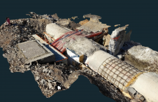
Time-of-flight technology works by sending out a laser pulse and measuring time taken to reflect it from an object back to the instrument. Combining the range with angle-encoder measurements provides the 3D location. These scanners are able to capture measurements at long range, to over 30 metres, and are the most popular with surveyors. Time-of-flight technology is simi-lar to the Direct Reflex (DR) or reflectorless technology used in advanced total stations. However, the difference between 3D scanners and DR technology is the speed of measurement. Total stations can measure around four distances per second in DR mode. In contrast, time-of-flight laser scanners can measure up to five thousand distances per second; that is over a thousand times the speed of a total station. This allows a 3D scanner to quickly produce large amounts of survey data. The resulting ‘point cloud’ can provide a 3D shape, or visualisation, of the object being measured.
Tool for the Future
To surveyors more familiar with measuring discrete points the sheer amount of data may seem overwhelming. The speed of measurement allows either significant reduction in survey field time or collecting a denser volume of points, which results in more accurate detail. In a similar way to early GPS technology, the first commercially available 3D scanners were used for specialised applications. As the technology has become more accessible and its benefits realised, surveyors have started looking to 3D scanners as a promising new tool. Increasing interest on the part of surveyors has led to manufacturers beginning to offer 3D scanning technology that is simple and efficient in use. Today’s 3D scanning technology also provides a workflow designed specifically for the surveying industry.
Previous Limitations
Traditional scanning methodology uses measurements to a number of common targets, either flat or spherical, to relate multiple scans to one another or to relate measurements to an existing control network. This workflow involves placing the scanner and measuring to a number of targets and objects, such as buildings. The scanner is then moved to a second location and at least three common targets, as taken from the first scanner location, are measured. This is necessary to relate the scans in a manner very similar to GPS calibration. The process is typically done in the office after completion of field-data collection. While traditional scanning methodology is suitable for many applications, it does have limitations:
- the scanner cannot be easily set up over a known point or directly related to a known point
- measurements have to be done to multiple targets from each scan location, which requires careful survey planning and time to measure each target
- multiple scans require field post-processing to relate the data into a single homo-geneous set, and to a control network.
Traditional Workflow
Older 3D scanners were large, not easily manoeuvrable and required a ground power supply and a PC or laptop for operation. To support the survey workflow, a modi-fied approach is required to 3D scanning hardware, software and methodology: one that resolves the above listed limitations. Basically, this can be achieved by using a traditional total-station survey workflow whereby the scanner is set up over known points to provide a direct relationship to control points. Measurements between stations (traverse measurements) provide an instant relationship between multiple stations and allow the user to view homogenous data in the field without post-processing. In order to support a survey workflow, 3D laser scanners must provide:
- tribrach with laser or optical plummet to ensure that the scanner is precisely positioned on a known point
- mark for accurately measuring the instrument height and field software that corrects instrument height measurement for the slope to obtain a true vertical measurement
- dual-axis compensator for levelling the instrument over a known point and which is able to actively correct the horizontal and vertical angles for mis-levelling
- centric-standard 5/8” thread mount in the top of the scanner for placing a prism or GPS receiver on top of it as part of an integrated survey solution, even during scanner operation.
In addition, 3D scanners should be equipped with advanced laser technology to provide accurate focused measurements and enhanced long-range operation. This technology ensures that the scanner can be used for a variety of survey applications and environments. Further, to enhance field portability 3D scanners should be equipped with a rugged field controller.
Adapted 3D Scanners
An integral part of a survey workflow is to efficiently relate measurements between stations and known control points. For this software is required. One of the most recent 3D scanners is the Trimble GX 3D Scanner which, coming with PocketScape field software, provides an example of how hardware and software can work together. PocketScape is designed to operate on a rugged field controller and fully supports typical scanning and survey workflows. The workflow available in 3D scanners such as the GX is close to standard fieldwork methods whereby a network of control points measured by GPS or total stations are also used as reference stations for the 3D scanner. Levelling of the GX and direct georeferencing of the point cloud is of great interest to surveyors, especially for outdoor projects.
Concluding Remarks
Newer 3D scanners are becoming robust, portable and have flexible power solutions. When used in a survey workflow, these scanners easily complement GPS and total-station techniques as part of a Connected Survey Site. For example, surveyors can use traditional survey techniques to establish a control network of known points and then use a 3D scanner for efficient data collection. 3D scanners of the future will all incorporate a survey workflow, at least for most outdoor scans where georeferen-cing of project data is required.
Further Reading
- Key, H., Lemmens, M., Laser Beam, Technology in Focus, GIM International, vol. 20, nr. 2, pp 13.
- Lemmens, M., Product Survey on 3D Lasermapping, GIM International, vol. 18, nr. 12, pp 44.
- Lemmens, M., van den Heuvel, F., 3D Close-range Laser Mapping Systems, GIM International, vol. 15, nr 1, pp 30.

Value staying current with geomatics?
Stay on the map with our expertly curated newsletters.
We provide educational insights, industry updates, and inspiring stories to help you learn, grow, and reach your full potential in your field. Don't miss out - subscribe today and ensure you're always informed, educated, and inspired.
Choose your newsletter(s)

