GNSS Positioning
Status and Features
Nowadays, GNSS receivers have scores – and often hundreds – of channels, enabling them to track GPS, Glonass, Galileo and Compass signals simultaneously. The whole workflow from satellite tracking to calculating the coordinates of the position in a preferred reference system can be conducted automatically in real time. The price of GNSS receivers has dropped steadily since the first GPS receivers came onto the commercial market in 1982. In conjunction with the latest product survey results for GNSS receivers (available at www.geo‑matching.com), the author puts today’s GNSS status and features in perspective.
(By Mathias Lemmens, senior editor, GIM International, The Netherlands)
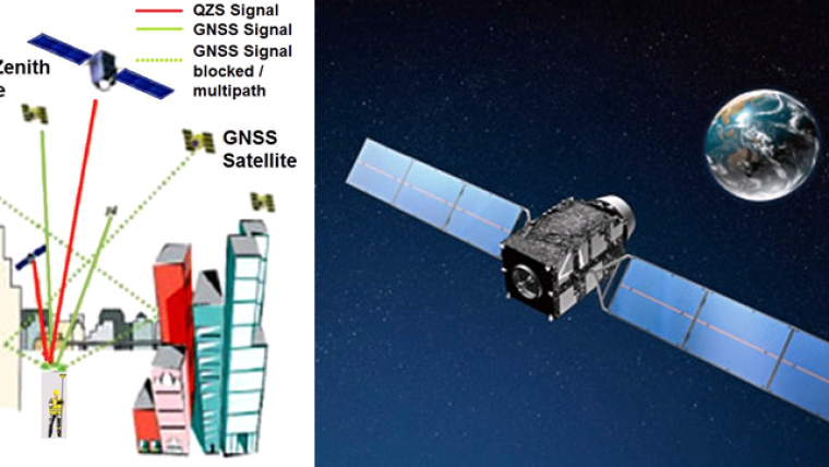
By 2020, there will be four fully operational GNSS constellations with global coverage: European Galileo and Chinese BeiDou (Compass) will have joined the American GPS, which has been complete and fully operational since July 1995, and the Russian Glonass, which has been complete and fully operational since October 2011. Meanwhile, India and Japan are working on regionally operating GNSS constellations. The Indian system will consist of seven satellites operating up to 2,000km around the boundaries of the subcontinent and enabling positioning with an accuracy of better than 20m. Japan is working on the Quasi-Zenith Satellite System (QZSS) designed to overcome positioning errors introduced by GNSS signals mutilated by high buildings in cities or steep mountain slopes. The QZSS satellites will fly in a near-zenith orbit over Japan, thus increasing the number of GNSS satellites in the line of sight in the vicinity of Japan (Figure 1). The first satellite, Michibiki, was launched on 11 September 2010. Once completed, the constellation will consist of three satellites.
Galileo and BeiDou
On 28 December 2005, Galileo’s Giove A was put into orbit, with Giove B following on 27 April 2008. On 21 October 2011, two Initial Operational Capability (IOC) satellites became operational and, at the time of writing (mid-September 2012), the second pair of Galileo satellites is being prepared for launch in October 2012. These four satellites have been designed to validate the Galileo concept both in space and on Earth. The full constellation will consist of 30 satellites (27 operational and 3 active spares).
From 2000 to 2007, China launched four navigation satellites, called BeiDou-1. Unlike its predecessors, the fifth satellite – launched 12 April 2007 – was not positioned in a geostationary orbit 35,800km above the Earth’s surface, but instead circles at an altitude of 21,500km. In 2009, this BeiDou-2 or Compass constellation was extended with a second satellite, then five more satellites were added in 2010, subsequently followed by another three in 2011, with the result that Compass has covered the Asia Pacific region since December 2011. China thus operates a GNSS system covering its territory with 13 satellites in orbit. The full constellation – due for completion by 2020 – will comprise five geostationary and 30 medium-orbit satellites intended to serve both civilian and Chinese government/military purposes. The free service for civilians will have 10m precision, which is lower than available for licensed users.
GPS Modernisation Programme
The GPS modernisation programme in the US is aimed at serving civilian users better. To reduce the effects of errors introduced by ionospheric delays, a receiver has to pick up at least two signals broadcasted at different frequencies. (Since the ionosphere influences signals depending on their frequencies, its effects can be removed by measuring two or more carrier signals. In contrast, tropospheric delays and orbital errors have the same effect on all carrier signals, irrespective of their frequencies.) For the US GPS constellation, these signals are L1 and L2, but only the C/A code carried by L1 is accessible to civilian users. The modernisation programme adds a second civilian-use signal – L2C – to L1. The first GPS satellite broadcasting L2C was launched on 26 September 2005 as part of the IIR(M) series of satellites (the M stands for ‘Modernised’). To explore L2C, a dual-frequency receiver is needed. The benefits will gradually increase as more satellites are put into orbit; as of June 2012, seven IIR(M) were operational. By 2016, full L2C capacity will be reached, with 24 satellites then broadcasting the L2C signal. To support the transportation sector in terms of safety-of-life transportation, fuel efficiency and capacity, a third civilian-use signal has been developed: L5, which has a signal twice as strong as that of L1 and L2C, thus enabling better penetration through trees and other objects that may block GNSS signals. L5 is transmitted by IIF satellites, the first of which was launched in May 2010. As of June 2012, two IIF satellites were operational, and by 2018 the full L5 capacity will be reached: 24 satellites will then be broadcasting the L5 signal. In addition to L1, L2C and L5, GPS will be expanded by a fourth civilian-use signal, L1C, starting in 2014. L1C will improve receipt beneath tree canopies and in urban canyons, thus allowing for more robust positioning. L1C will reach full capacity by 2021.
Glonass
By 2010 Glonass satellites covered the entire Russian Territory, and in October 2011 Glonass was augmented with another four satellites which restored the constellation to its full 24 satellites. (Lack of economic impetus had resulted in the full constellation – which was initially completed in 1997 – diminishing to leave just eight satellites in orbit by April 2002. Full global coverage could have been re-accomplished in early 2011had the launch of the completing Glonass-M satellites succeeded on 5 December 2010. However, the launch rocket splashed down in the Pacific Ocean.) Achieving full global coverage is one thing but stimulating the use of the system by the world’s citizens requires more effort. As a way of supporting Russian manufacturers of portable navigation devices while also stimulating Glonass compatibility, the Russian authorities are considering introducing financial incentives by charging import duty on all portable devices able to pick up GNSS signals, including smart phones and car navigation systems, unless they can process Glonass signals. The measure has been under discussion for some time, with a duty of 25% being suggested back in mid-2010.
Many firms already manufacture GNSS receivers or OEMs (see box) that are able to track Glonass signals. Septentrio offers multi-GNSS OEMs. Its AsteRx3 (see Figure 2), for example, has 136 channels and can simultaneously track GPS, Glonass and Galileo signals, plus it is also ready for Compass. Javad’s Quattro-G3D, to mention just one of the many GNSS products from this stable, has 216 channels and can track GPS L1/L2/L2C, Galileo E1 and GLONASS L1/L2 signals. The C-Nav’s 3050 DGNSS receiver has 66 channels and tracks GPS, Glonass and Galileo signals. The receiver combined with a subscription provides decimetre accuracy worldwide between 72°N and 72°S in air, on land and at sea. Today, virtually all manufacturers produce high-end GNSS receivers able to track Glonass signals, including in addition to the above Ashtech, CHC, Hemisphere, Hi-Target, Leica, Novatel, South, Stonex, Suzhou, Topcon and Trimble.
DGNSS and RTK
The features of the GNSS receiver are just one component in the entire trajectory from tracking L1, L2C, L5 and all the other signals to achieving precise and reliable positioning. One may be using a highly sophisticated receiver, but if the receiver has to operate in an environment with underdeveloped infrastructure, it may significantly underperform, just like an expensive racing car would struggle through muddy and hilly terrain. Improving the precision and reliability for GNSS users requires the running of separate augmentation systems. This is why firms such as Leica, Trimble and C-Nav deliver not only hardware and processing software but also solutions to eliminate errors introduced by ionospheric and tropospheric delays, the receiver clock and satellite orbits to enable precision at the decimetre or even (sub)centimetre level combined with high reliability and repeatability.
The solutions originate in introducing an additional GNSS receiver, called a base station, positioned above a point with known coordinates. Next, these known coordinates are compared with those measured with the GNSS receiver at the base station. When the atmospheric distortions and other error sources are more or less the same for the base station and the rover position – this will be so if the locations of base and rover are not too distant – the corrections computed for the base will also be valid for the rover. The closer the two, i.e. the more resemblance between the atmospheric conditions (and hence distortions), the better the corrections will fit. Such differential corrections may be transmitted in real time by radio link, mobile phone or wireless internet to the rover, enabling instant capturing of position. When using code ranging alone, the precision of DGNSS is around 30cm to 50cm. When carrier phase measurements are added to code ranging – Real Time Kinematic (RTK) – sub-centimetre level precision can be achieved. Nowadays, RTK is widely used for surveying and other precise positioning. In single base station RTK, the errors are assumed to have high spatial correlation and thus be constant around the base station. However, the greater the distance from the base, the less this assumption holds true. The maximum distance between rover and base station is conventionally set to 15km; at larger distances, the quality degrades rapidly.
Network RTK
In many areas, surveyors themselves do not need to set up a base station and invest in two geodetic GNSS receivers since public agencies and private companies have already established networks of GNSS receivers positioned on reference points. These networks of Continuously Operating Reference Stations (CORS) are available round the clock and allow the use of only one receiver without compromising precision and reliability. A temporary failure of the communication link or the GNSS receiver on one base station will not affect continuity as the other base stations are still in operation. Today, commercial Network RTK (NRTK) is an essential GNSS infrastructure for centimetre-level positioning, which is achieved when the base stations are less than 70km-100km apart.
The above gains come at a cost: one often needs a paid subscription to access to NRTK corrections. As an example, Leica Geosystems offers an annual subscription to SmartNet NRTK for around USD2,400. However, networks run by public agencies, such as the US Coast Guard system, are usually offered free of charge, particularly for navigation purposes. The diverse commercial services generate RTK corrections based on differing concepts, including Virtual Reference Station (VRS), Pseudo-Reference Station (PRS), FKP (an acronym of the German term FlächenKorrekturParameter meaning area correction parameters), and Master-Auxiliary Concept (MAC) and its refinements MAX and i-MAX. VRS and MAC are the two most prevalent methods.
VRS and MAC
Basically, NRTK works as follows (Figure 3): base stations and rovers use GNSS signals stemming from common satellites. As the main observable is the carrier phase, the ambiguities between the base stations have to be resolved at a network server. Next, the rover picks up the corrections to correct its own observations, or the rover sends its initial location to the server and then the rover-specific corrections are transmitted to the rover (VRS concept). The VRS concept creates one virtual base station in the vicinity of the initial rover location for which corrections are computed using information from the entire network, which consists of at least three base stations (Figure 4). These corrections are transmitted to the rover, which requires two-way communication. However, the rover does not need to carry out complex computations, and it uses the corrections as if they had originated from one real base station.
In the MAC method, the rover has much more flexibility in conducting the RTK solution. Either a simple interpolation of the network corrections may be used or more exact calculations conducted. In principle, the MAC method only needs one-way communication, since the rover merely has to pick up the correction data calculated and disseminated by the network server. To reduce data volume, full corrections and coordinate information are sent for only one base station – the master station – while correction differences and coordinate differences are transmitted for the auxiliary stations. The master station is not necessarily the base station closest to the rover, although it is in a refinement, called auto master-auxiliary corrections (auto-MAX). Auxiliary stations are chosen from the surrounding base stations such that an optimal solution can be generated given the rover’s approximate position. Hence, Auto-MAX requires two-way communication. A further modification has been introduced for older rovers not capable of using RTCM 3.1 NRTK messages, called individualised MAX (i-MAX). RTCM (Radio Technical Commission for Maritime Services) is a standard for transmitting real-time corrections to GNSS rovers. The i-MAX method is similar to VRS in so far as both use one master station, but i-MAX generates corrections for a real reference station instead of a virtual one (Figure 5). The commercial NRTK service available from Leica – SmartNet – is based on the MAC method. Trimble supports establishing NRTK based on VRS.
SBAS
In addition to ground-based communication links, satellites are used to submit differential corrections to GNSS receivers. These Satellite Based Augmentation Systems (SBAS) also send corrections derived from measurements taken at base stations. However, these corrections are now sent to one or more satellites which broadcast them to enabled receivers. Sub-metre precision in real time could be achieved by connecting to an SBAS. One such system, initially developed for air navigation purposes, is WAAS (Wide Area Augmentation System), the SBAS of the US. Its network consists of around 25 base stations distributed throughout the US, and the corrections are broadcast to two geostationary satellites. Europe has developed the Euro Geostationary Navigation Overlay Service (EGNOS) with a network of 34 base stations and communication links through three geostationary satellites. The Asian continent will be covered by the Japanese Multifunctional Satellite Augmentation System (MSAS) and India’s GPS-Aided GEO Augmented Navigation (GAGAN) Technology Demonstration System. The above are public-funded initiatives; Figure 6 indicates their coverage. OmniSTAR offered by Fugro serving offshore and land-based applications, and John Deere’s StarFire system aimed at precision farming, are both commercial SBAS services.
Outlook
People spend 80% to 90% of their time indoors, where GNSS signals are too weak to be picked up by receivers. In response, extensive research is ongoing to develop GNSS-less positioning systems using nearby or distant beacons to provide locations in every nook and cranny of urban conglomerates. Distances or angles from receivers to beacons are used as measuring quantities, enabling calculation of position estimates through techniques such as trilateration or triangulation. The future of positioning would look bright, were it not for the fact that it is becoming very crowded in the microwave part of the electromagnetic spectrum (say wavelengths from 1cm to 1m), while nearby GNSS frequencies are heavily overcharged. Hence the demands and interests are huge, and there could be a frequency war looming.
In conjunction with this article on the status and features of GNSS, the latest product survey of GNSS receivers is available at www.geo-matching.com.
OEM
The term Original Equipment Manufacturer (OEM) indicates products used by manufacturers who incorporate them into goods of their own, which they then take to market under their own brand name. The use of OEM products has also found its way into GNSS receivers, antennas and services. Some manufacturers, such as Leica and Trimble, introduce OEM receiver boards – such as the BD960 which is able to track GPS L2C and L5 and Glonass L1/L2 signals – antennas and software onto the market in addition to complete GNSS receivers aimed at high-end users. Other producers such as Hemisphere GPS, Novatel and Septentrio focus on delivering OEMs to customers in a wide range of industries, including transport, construction, mining, agriculture and the military, for the purpose of adding positioning functionality to oil tankers, trucks, paving machines, bulldozers, shovels, mowers, jet fighters and many other vehicles.
Biography of the Author
Mathias Lemmens holds an Ir. (MSc) degree in geodesy and received his doctorate from Delft University of Technology, The Netherlands, where he presently holds a post as assistant professor. He operates as an international consultant focused on emerging and developing countries. He was editor-in-chief of GIM International for 10 years, and now contributes as senior editor.
Email: m.j.p.m.lemmens@tudelft.nl
Further Reading
- Janssen, V., 2009, A comparison of the VRS and MAC principles for network RTK, IGNSS Symposium, Queensland, Australia.
- Lemmens, M., 2011, Geo-information: Technologies, Applications and the Environment, Chapter 4, Springer, ISBN 978-94-007-1666-7

Value staying current with geomatics?
Stay on the map with our expertly curated newsletters.
We provide educational insights, industry updates, and inspiring stories to help you learn, grow, and reach your full potential in your field. Don't miss out - subscribe today and ensure you're always informed, educated, and inspired.
Choose your newsletter(s)