Laser Scanner in a Backpack
The Evolution towards All-terrain Personal Laser Scanners
Laser scanning systems have gone through a major evolution in the past decade. After the initial breakthrough of airborne laser scanners (ALS), other types of laser scanning systems have emerged, most notably terrestrial laser scanners (TLS) and mobile laser scanners (MLS). While these three main types of Lidar systems together serve a large number of applications, none of them are optimised for fast and flexible scanning in challenging locations, rugged terrain and complicated urban structures. Personal laser scanners (PLS) fill this void and are now evolving towards compact, agile and flexible solutions for mapping complex environments. This article explains the new Akhka R2 PLS and illustrates its use in various applications.
(By Antero Kukko, Harri Kaartinen and Juho-Pekka Virtanen, Finland)
Need for new 3D data collection tools
Many applications require 3D data of objects and their surroundings. Examples can be found in civil and industrial engineering, road construction and maintenance, urban planning, environmental analysis and precision forestry. Lidar has been widely used throughout the years to scan objects or map the environment in 3D to support these applications. The ALS, TLS and MLS types of Lidar systems each have their own applications and advantages and disadvantages. However, there are situations in which none of these Lidar systems can be used. For example, fences, curbs or the orientation of a passageway may prevent access with a MLS, or the terrain may be too rough or too spatially limited. A TLS, on the other hand, may be suitable for the terrain but may be inadequate due to the limited number of viewpoints and the requirement of excessive data redundancy for successful scan registration. Therefore, the growing need to model and monitor objects in complex environments is challenging the industry to develop new 3D data collection tools that are even more complete, accurate and efficient.
Heavy prototype but easy for rough terrain
The need for an agile field MLS for large-scale geomorphological landform surveys was the driving force behind the development of the backpack mobile laser scanning system called Akhka that is described in this article. This PLS essentially has similar mapping capabilities to an MLS. The first prototype of the Akhka PLS was built in early 2011 and it was operated in the Finnish Arctic region for mapping point bars (inside-bend river deposits) and palsa landforms (Arctic frost heaves). The prototype proved to be functional and a good starting point for further improvement. One feature still requiring a lot of attention, however, was the weight of the system, since it was too heavy to be worn comfortably for long periods. Nevertheless, operators could easily complete two-to-three-hour mapping runs on loose sand and rugged terrain.
Akhka revision
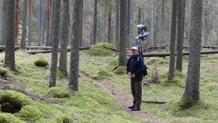
The current production version of the Akhka PLS, Akhka R2 (Revision 2), now has a much lighter scanner unit and a more robust solution for the trajectory determination with multi-constellation global navigation satellite systems (GNSS) coupled to a fibre optic gyroscope (FOG) inertial measurement unit (IMU). The basic version uses the FARO Focus3D 120S scanner operating at 905-nanometre laser wavelength. The laser scanner on the system operates on profiling mode scanning cross-track profiles behind the operator with slightly forward tilt. 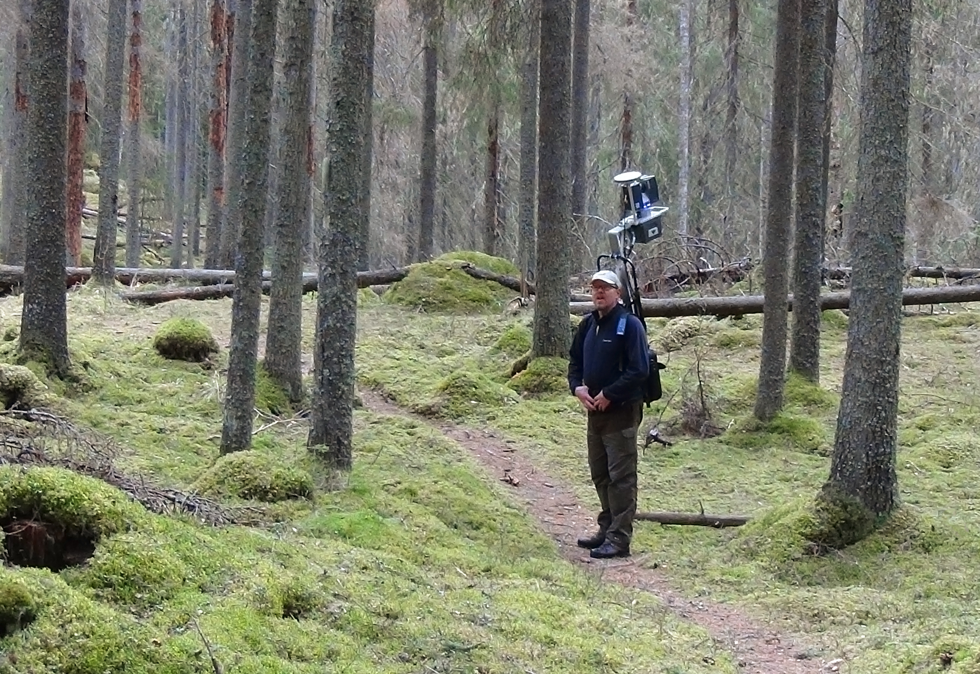
In Figure 1, the GNSS antenna (white plate) is seen on top and the IMU is found below the scanner. A rugged tablet computer is used to store the positioning and timing data; the scanner data is stored on SD memory cards in the scanner. Table 1 gives a summary of the Akhka R2 sensors.
|
Sensor type |
Model |
Characteristics |
|
GNSS Receiver |
NovAtel Flexpak6, 702GG antenna |
GPS L1, L2, L2C, L5; GLONASS L1, L2, L2C |
|
IMU |
Northrop-Grumman Litef UIMU-LCI |
Fibre optic gyroscopes, MEMS accelerometers |
|
Scanner |
FARO Focus3D 120S or X330 |
976,000 points/s, 95 profiles/s |
|
Computer |
Panasonic Toughpad FZ-G1 |
WIN-8.1, 10.1" WUXGA, SSDrive |
Table 1, The sensors in Akhka R2 used for integrated positioning and laser scanning.
Easy mounting
The whole scanning system is designed as one backpack-sized sensor pack. The idea of the sensor pack is to have all the sensors mounted rigidly onto a single and compact bundle to maximise robustness and minimise platform distortions and the need for calibration. The R2X version of the Akhka PLS is a slightly modified version of the Akhka R2, which uses 1,550 nanometre laser light for ranging. This category includes the long-range versions of the FARO Focus3D family of scanners, such as the X330 with an ambiguity range of about 300 metres but also the X130 model with a ranging ability of up to 150 metres. These scanners essentially have the same physical dimensions as the 120S version, so mounting any of them to the Akhka R2 platform is straightforward. The structural design of the sensor pack supports the option for vehicle mount as well, allowing even more versatility in different environments and for various data needs.
Precise forest coverage
 The PLS allows the operator to move in and around the scene while capturing the environment with millimetre precision. This is an essential feature when mapping a forest. Figure 2 shows a forest scene captured with the Akhka R2X system. The plot was collected by walking through the forest in different directions to create a dataset with complete coverage. The data shows detailed features of the forest stand (a collection of trees with similar characteristics) and terrain for precise tree stem count, volume and canopy cover estimation and biomass calculation.
Impact craters
Acquiring data with a PLS makes it possible to capture all terrain details that are needed for the analysis and understanding of specialised activities like impact cratering and planetary analogue missions. In addition, PLS systems can be used to supplement data or to validate data from smaller-scale sensor systems. Figure 3 illustrates a point cloud collected from the Kaali impact crater in Saaremaa, Estonia, to map the 3D shape and size of the crater. Along with the overall model created from the point cloud, the high-density scan data could also be used to relate the crater features to the size of the impactor.
Flooding
In fields such as fluvial geomorphology and other natural processes generated by water, wind, frost or ice, a PLS can produce detailed data for relating the extent of change in 3D to other monitored processes such as flooding or wind (speed and direction). 
Figure 4: Section of Rambla de la Viuda in Spain representing the erosion ravine induced by a flooding event.
For example, the hydraulic modelling of a riverine system benefits greatly from a detailed reconstruction of flooding periods to relate discharge and river bed characteristics. A small ravine eroded by a flooding event (Figure 4) at Rambla de la Viuda, Valencia, Spain, was captured with Akhka R2 to reconstruct the changes induced by the flooding and to derive environmental parameters (such as surface roughness) for hydraulic modelling.
Urban mapping

Figure 5: Urban scene mapped with a PLS
Furthermore, a PLS can be used for urban mapping and industrial engineering. The PLS can capture the fine details of structures thanks to its high level of mobility. The speed of data collection helps in precise scheduling of tasks. In addition, the PLS minimises the need for process breaks, thus making it ideal when conducting surveys in busy streets and industrial environments. The 3D reconstruction of urban areas (Figure 5) can be used for as-built documentation and planning of new structures and buildings in great detail.
Future
It is expected that PLS systems, essentially the ‘MLS in a backpack’, will be used extensively for a wide range of applications that require data with a high level of detail for structural reconstruction and analysis. Sensor technology is making systems smaller and smaller, thus aiding operations both in the field and indoors, provided that integrated computational technologies evolve sufficiently to also enable accurate positioning in GNSS-denied environments. There are some very interesting small sensors already available in the market and integrated systems are being launched on a commercial basis. However, the main factors to be considered in the system design for a given application are point and line measurement rates, ranging capability and resolution along with angular resolution. There is much still to be done in terms of finding the optimal sensor layout and performance levels for each and every application, but personal laser scanning is definitely a technology to keep an eye on.
Authors
Dr Antero Kukko is a research manager at the Finnish Geospatial Research Institute and at Aalto University. His research includes the development of mobile laser scanning systems, performance, data calibration and processing.
Prof Harri Kaartinen from the Finnish Geospatial Research Institute coordinates and conducts research on performance and quality issues related to laser scanning sensors, systems and applications.
M.A. Juho-Pekka Virtanen is currently working at the Institute of Measuring and Modelling for the Built Environment at Aalto University. His research topic is regional information modelling and applications of laser scanning.
Figures
Figure 1, The Akhka R2 PLS system is suitable for detailed mapping of rugged terrain and complex scenes such as forests. The system consists of a laser scanner, GNSS-IMU navigation system, a tablet computer for data recording and a support structure, all carried as a backpack for flexible operation.
Figure 2, Forestry data collected with the Akhka R2X. The system captures not only the ground surface and dominant trees for stem and canopy modelling, but also the secondary forest layer. The PLS allows for easy access to and complete data coverage of complex environments. Image colouring is based on laser intensity while the white line shows fractions of the data collection trajectory.
Figure 3, Thinned point cloud representation of the Kaali impact structure computed from the Akhka R2 data. Point colouring represents the point intensity and order of data collection in terms of block number (0-42). The rim of the 25m-deep crater is 110m in diameter. Data collection trajectories are plotted in blue for the post-processed GNSS-IMU and in red for the one corrected based on target data.
Figure 4, Section of Rambla de la Viuda in Spain representing the erosion ravine induced by a flooding event. The scene is captured with the Akhka R2. The data acquired with the backpack scanning platform can be used as input data for hydraulic modelling. The point colouring represents the ground elevation. To show the scale of the scene, the person captured in 3D in the top centre of the image is 1.8m tall.
Figure 5, Urban scene mapped with a PLS. The PLS enables collection of complete data from the built environment (e.g. for management and renovation purposes). The operator could use stairs and gateways to reach sections not visible from the street.

Value staying current with geomatics?
Stay on the map with our expertly curated newsletters.
We provide educational insights, industry updates, and inspiring stories to help you learn, grow, and reach your full potential in your field. Don't miss out - subscribe today and ensure you're always informed, educated, and inspired.
Choose your newsletter(s)


