Recent developments in close-range photogrammetry
A measurement technology in transition
Dramatic advances in automatic digital image analysis have opened up new applications and made photogrammetry applicable for a broader field of users that lack specific knowledge of photogrammetry. Megatrends such as Industry 4.0, building information modelling (BIM) and the digital transformation are driving the advancement of 3D measurement technologies, both in terms of high-end systems and low-cost sensors. New technical challenges such as autonomous driving or unmanned aerial vehicles are demanding innovative sensor systems, but also extended maps and models of the environment. Modern approaches such as structure from motion (SfM), simultaneous localization and mapping (SLAM) or visual odometry are now being combined with classical photogrammetric methods. This article addresses these and other recent developments in close-range photogrammetry.
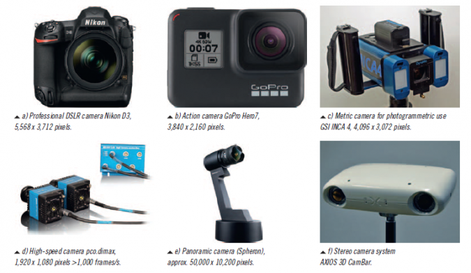
New technical challenges such as autonomous driving or unmanned aerial vehicles (UAVs or ‘drones’) are demanding innovative (hybrid) sensor systems, There is a huge range of image-recording devices available for close-range photogrammetry purposes (see Figure 1 for a few examples). Typical sensors can be roughly classified as follows:
- Action and fisheye cameras
- Cameras for the consumer market
- Cameras for professional applications
- Industrial cameras
- Metric cameras for explicit photogrammetric applications
- High-speed cameras
- Panoramic cameras
- Multi-camera systems
Practically all modern imaging sensors are designed based on CMOS technology. Their availability ranges from mass products, e.g. smartphone cameras (usually with a rolling shutter), to specific high-performance sensors used for special applications such as high-speed imaging. Sensors with a global shutter are required for most dynamic applications where the camera or object are moving with respect to each other.
Hybrid sensor systems
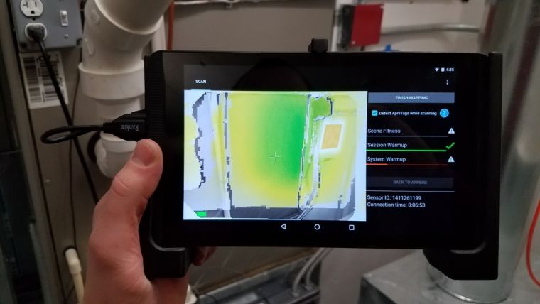
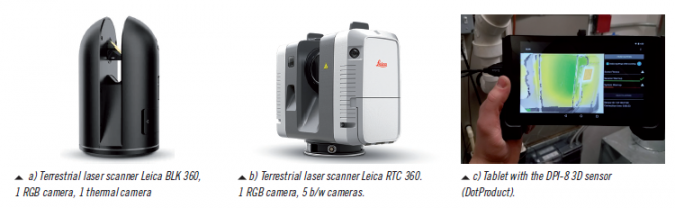
An increasing number of hybrid systems are available in which camera sensors are combined with additional measuring devices. The most popular examples are terrestrial laser scanners equipped with one or more cameras for the acquisition of panorama images or for recording colour values for each point of a laser scan. As an example, the Leica BLK 360 scanner (Fig. 2a) consists of an additional thermal camera that can measure temperatures. The new Leica RTC 360 scanner (Fig. 2b) consists of five cameras that are used for visual odometry in a SLAM approach in order to measure the way and pose when the scanner is moved to the next station. Other examples of hybrid systems are low-cost sensors running on tablets or mobile devices that combine IMU, GNSS, time-of-flight (ToF), laser triangulation or RGB cameras for low-to-medium-accuracy 3D scanning. Fig. 2c shows a handheld tablet device based on a ToF sensor.
Camera calibration
Almost every kind of camera can be used for photogrammetry as long as the interior orientation (camera parameters) can be calibrated. In particular, the functional model for modelling lens distortion and other imaging errors must be chosen appropriately to the specific camera. Depending on the stability and reproducibility of the camera geometry, it can be calibrated prior to or after a measurement if there is no ability for self-calibration on the job. Examples are measuring systems with a fixed arrangement of cameras in a housing. Examples of highly stable metric cameras are given in Fig. 1c and Fig. 1f. Artificial test fields are usually applied here for pre-calibration which should have a three-dimensional distribution of targets to provide a reliable and full calibration of the camera with minimum correlations to exterior orientations. For a large number of applications, the camera can be calibrated simultaneously with 3D object reconstruction by bundle adjustment. In this case, the camera is calibrated for the time of object recording, hence without any assumption of validity of previous calibration parameters. This approach is included in standard photogrammetric offline systems, e.g. SfM.
Measurement of tie points
Multi-image photogrammetry requires overlapping images which are connected by corresponding points (homologous or tie points). By means of targets, which may be coded to define a certain point number, the process of finding correspondences and approximations for orientation is relatively easy. Using natural features as tie points, certain detectors and descriptors allow for the matching of similar features using different criteria. As examples, operators like SIFT, SURF or ORB provide robust feature detection and matching. However, for a reliable match it is recommended to acquire the images with a large relative overlap, e.g. 90% from image to image. Matching becomes weak or even impossible if large object areas are imaged without sufficient textures.
Orientation
The calculation of the exterior orientations of all images (also called alignment) is a prerequisite for subsequent 3D object reconstruction. Basically, the process starts with a complex procedure for finding approximate values of all unknown parameters by a clever combination of relative and absolute orientations, space resections and intersections. The final optimization of all parameters is done by bundle adjustment which minimizes the residuals of all observations (image measurements) in one process in order to determine the desired calibration and orientation parameters, and the 3D coordinates of all tie points. If control points are available, they are integrated to define the final coordinate system and to compensate for the datum defect of a photogrammetric network. The 3D coordinates of all measured points provide a sparse point cloud of the object surface.
Bundle adjustment is the critical part in a photogrammetric orientation process. Hence, statistical quality parameters (sigma values, RMS of object points) shall be analysed carefully to provide a picture of the internal precision of the adjustment. However, the real accuracy must be checked by independent reference values (see below).
SfM and SLAM
Basically, the structure-from-motion approach is a complex procedure where subsequent images with high overlap are oriented automatically by means of feature detection, feature matching and robust sequential orientation. Based on RANSAC-based procedures and linear estimation models, datasets with a high number of outliers can be processed sufficiently.
Simultaneous localization and mapping (SLAM) approaches are often used in dynamic environments (e.g. moving robots) to measure the route (pose) of the sensor and the unknown environment simultaneously. Image-based SLAM algorithms are also called ‘visual odometry’. Since the geometric configuration of image sequences is often weak, additional sensors (e.g. IMU) and Kalman filtering are included.
Dense point clouds
After successful bundle adjustment, a dense point cloud of the object surface can be calculated, if necessary. The objective is to derive 3D coordinates for every pixel (or in a specific resolution in object space). Today, the most successful approaches are based on semi-global matching (SGM) which looks for best matches along epipolar lines by minimizing a particular cost function. SGM is a robust method that can interpolate textureless areas and create surface models that sufficiently preserve sharp edges in object space. Compared to the orientation process above, the generation of dense point clouds requires much higher computational effort.
Orthophotos
Even in close-range photogrammetry, the generation of (true) orthophotos has become an important product, especially for UAV applications or in architectural and archaeological projects. Since the process described above generates orientation parameters and a dense surface model, orthophotos can be derived directly from the acquired images. However, a photogrammetric point cloud usually describes the visible surface of the object, i.e. with vegetation or other disturbing objects included. Before a final true orthophoto can be produced, the surface model may be subject to (manual) cleaning, filtering or other types of post-processing.
3D modelling
In many applications, further processing of point clouds is required, e.g. for the production of architectural plans or 3D models for BIM or facility management. Although a number of semi-automated software approaches are available for the extraction of certain elements (e.g. planes, pipes), the generation of final products often requires manual processing. This holds true for any kind of point clouds, i.e. also from laser scanning or other technologies.
Semantic modelling, i.e. automatic classification of object parts, is still an ongoing research task that must involve human knowledge of the object and the application. Recent machine learning approaches demonstrate promising solutions to solve at least a part of the modelling interpretation process.
Accuracy and verification
Professional use of photogrammetry usually involves specifications for high-quality results. In industrial applications, the verification of the achieved accuracy with respect to accepted guidelines is most important. In most cases, standardized characteristics such as the maximum length measurement error have to be reported including retraceability to the standard unit metre, e.g. by measurement of calibrated reference artefacts. In non-industrial fields, e.g. cultural heritage or topographic surveying, the comparison of independent control points is a well-established method to derive accuracy figures. However, these points should not be included into orientation processes but should be measured individually in order to represent subsequent processes such as dense matching.
Example: Robot-based industrial inspection
Industry 4.0 is characterized by a number of significant changes in production, e.g. higher degree of individual products, shorter life cycles or more flexible manufacturing lines. For the past two decades photogrammetry has been successfully used in high-precision industrial metrology, e.g. in fields like inspection of tooling jigs by offline photogrammetry. Other examples include image-guided manual probing for measuring single 3D points with a touch probe, or fringe projection systems used as a standard tool for free-form surfaces.
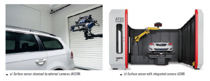
A new direction of online systems uses robots to drive a surface sensor to specific areas of an object. Since the mechanical positioning accuracy of a robot is not high enough to provide the exterior orientation (pose) of the scanning device directly, a camera system observes the actual position of the sensor with respect to a pre-calibrated field of targets. This concept provides high flexibility to adapt for specific measurement conditions. Hence, it allows the integration of optical 3D measurement devices into flexible production lines.
Figure 3a shows a system in which a set of ceiling-mounted cameras measures the 6DOF pose of a fringe projection system. Figure 3b illustrates a robot-based system in which a camera is attached to the surface sensor which permanently measures a set of reference targets.
Example: UAV photogrammetry
UAV-based photogrammetry has become a standard measuring technology now that remotely piloted drones with high capabilities for autonomous flying are available. With the relevant flight permissions, UAVs can be used as imaging platforms for a wide area of applications, e.g. road mapping, observation of construction sites, archaeological surveys, topographic mapping, environmental monitoring, etc. In most cases, recorded images are processed by SfM software that automatically generates point clouds or orthophotos.
Since many users have only limited photogrammetry skills, they do not always properly understand the impact of image configurations, distribution of control points or camera calibration issues. Consequently, the quality of results not only varies from project to project, but can also vary within a certain area of measurement within a project.
The professional use of UAV photogrammetry usually requires a high-quality camera/lens system, camera stabilization, dense image overlaps, sufficient intersection angles and a suitable distribution of control points, just as with aerial photogrammetry. Camera calibration can be particularly difficult when using non-professional cameras and/or weak flight configurations.
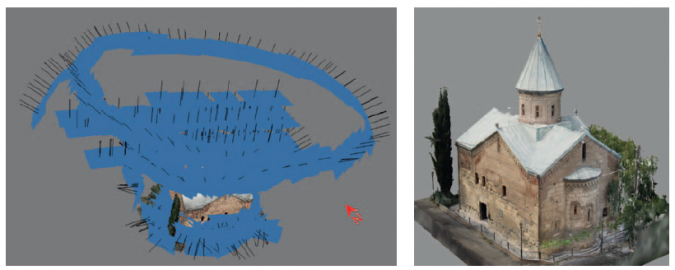
Figure 4 shows an example of the use of an amateur drone (DJI Mavic Pro) for recording the roof areas of an ancient church. Although the drone was guided manually and the camera is not designed for measurements, configuring flights at different heights and the additional circular arrangement of images enabled the simultaneous calibration of the camera. Together with additional terrestrial images taken with a 24MP DSLR camera, a consistent and accurate 3D model with an average accuracy of 0.6 pixels (GSD between 5-10mm) could be generated by an SfM approach (RealityCapture).
Example: Underwater weld measurement
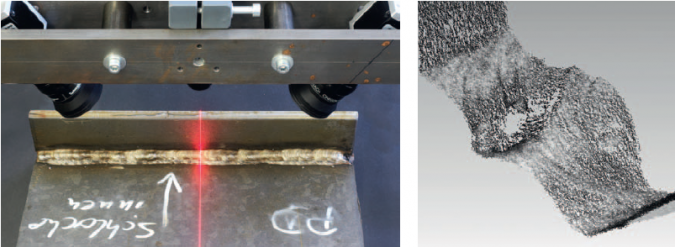
In this example of measuring welding seams of underwater steel constructions, the objective is to measure the surface of welds with an accuracy and a resolution of about 30µm in a distance of about 50mm. Two variants of a prototype system have been developed. One solution consists of a laser line projector and two cameras that observe the projected laser line for stereo matching. The second version uses one or two cameras that are moved across a reference field with control points in order to derive the exterior orientations. The surface within overlapping areas is reconstructed by photogrammetric image matching.
Conclusion
Recent trends and developments from photogrammetry and computer vision indicate a continuous change of classical measurement technologies which could be classified as a paradigm shift. A wide area of new applications is now addressed, leading to new prospects and challenges. However, whilst new automated imaging technologies increasingly cover dynamic scene recordings, the proper use of these methods by users with limited skills may lead to unsafe or unforeseen results. Hence, appropriate teaching concepts for students as well as life-long learning offers for practitioners are urgently required.
Further reading
Fryer, J.G., Mitchell, H.L., Chandler, J.H. (2006): Applications of 3D measurement from images. Whittles Publishing, Caithness, Scotland, UK.
Luhmann, T. (2018): Nahbereichsphotogrammetrie. 4. Auflage, Wichmann Verlag, Offenbach/Berlin, 783p.
Luhmann, T., Robson, S., Kyle, S., Boehm, J. (2019): Close-Range Photogrammetry and 3D Imaging. 3rd edition, de Gruyter, Berlin, in press.
Stylianidis, E., Remondino, F. (eds.), 2016: 3D Recording, Documentation and Management of Cultural Heritage, Whittles Publishing, 388 p.

Value staying current with geomatics?
Stay on the map with our expertly curated newsletters.
We provide educational insights, industry updates, and inspiring stories to help you learn, grow, and reach your full potential in your field. Don't miss out - subscribe today and ensure you're always informed, educated, and inspired.
Choose your newsletter(s)


