Sensor Fusion for Precision Agriculture
Low-cost Lidar Camera System without GNSS
Precision agriculture has considerably benefited from the use of unmanned aerial vehicles, often combined with active ranging sensors like Lidar to gather information from underneath the crops, but existing systems are relatively expensive for the farming sector. In this project, researchers in Canada have used an integrated sensor orientation method for the local referencing of Lidar measurements. Their approach is based on loosely coupled, image-aided inertial navigation in which the pose of the camera replaces the GNSS measurements. The result is a low-cost solution that is useful for capturing topographic data of inaccessible areas as well as in GNSS-denied environments.
One of the major components of agricultural automation is formed by sensors, which are required for both monitoring the condition of productions (precision agriculture) and facilitating the navigation and deployment of farming machinery (agricultural robotics). Precision agriculture has considerably benefited from the use of unmanned aerial vehicles (UAVs or ‘drones’) to address a variety of fine-scale mapping problems such as monitoring crop health, modelling field biophysical attributes and studying soil characteristics including soil micro-topography. Micro-topography defines topographic variability and describes soil surface variations. This attribute plays a significant role in many agricultural phenomena, such as run-off, erosion, aggregate stability, surface storage, infiltration capacity and vegetation dynamics. The primary challenge for quantifying soil micro-topography at plot scale includes access to accurate and complete elevation measurements from the bare soil at high horizontal resolution (1-3cm). Passive imaging such as in UAV photogrammetry acquired at low altitudes is a suitable solution to address this challenge. The use of structure from motion (SfM) techniques and multi-view stereo reconstruction allows the creation of high-resolution, high-accuracy and high-precision 3D point clouds of the environment from unmanned aerial imagery.
Soil microtopography sensors
However, sensitivity to environmental conditions as well as the inability of passive imaging to gather information from underneath the crops necessitates the (additional) use of active ranging sensors, like Lidar. Photogrammetric 3D point clouds can be complemented by Lidar point clouds to include additional geometric information. For example, a distinction can be made if the Lidar sensor provides multiple returns: one from the top of the vegetation and, possibly, one from lower elevations, e.g. bare soil.
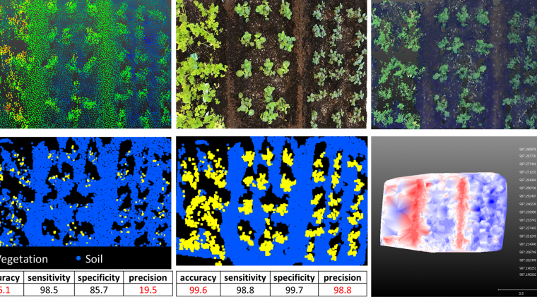
Several studies have compared the pros and cons of 3D reconstruction of agricultural attributes using photogrammetry versus laser scanning. The briefest conclusion is that there is no technology which is thoroughly robust against all sources of error and noise caused by the sensors and/or the environment. Examples are brightness variations, shadows, weather conditions, reflectivity variations, dynamic objects (vegetation moving in the wind), partial and total occlusions and perspective distortions (oblique versus nadir imagery). Therefore, integrating a digital camera and a Lidar sensor on board a UAV is a practical solution for measuring soil micro-topography. Figure 2 shows an example of integrating Lidar data with colour information from imagery and densifying the data by photogrammetric point clouds. 3D points corresponding to vegetation are automatically separated from soil points (a.k.a. ground filtering) using supervised classification via support vector machines, and a highly detailed digital terrain model (DTM) is reconstructed.
Sensor integration and data fusion
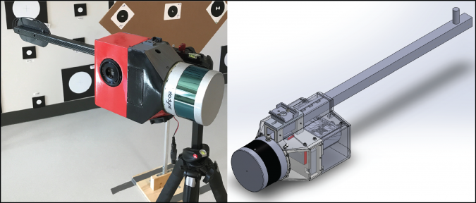
Therefore, a system was developed that integrates passive imaging and active ranging sensors. The total cost of building this integrated system is under CAD15,000, including an optical digital camera (a6000, Sony), a 3D Lidar capable of obtaining two returns (VLP-16, Velodyne LiDAR Inc), an inertial navigation system (VN-200, VectorNav Technologies), a compact processor, electronic components and the casing.
To measure georeferencing accuracy, one needs ground checkpoints, i.e. points with known 3D coordinates not participating in the bundle adjustment process as a ground control point (GCP). GCP errors are the residuals of the bundle adjustment and are not representative of the reconstruction accuracy nor the georeferencing accuracy; they merely show how well the mathematical photogrammetric equations are fit to the observations. In this project, the researchers did not test the georeferencing accuracy as the data was positioned relatively in space. What is important for soil micro-topography is the internal consistency of the positions obtained at various moments during the survey. The sensors and the system were geometrically calibrated and, with an integrated sensor orientation solution, the georeferencing accuracy achieved is better than 1cm within a local coordinate system.
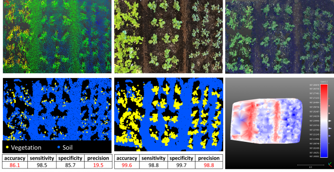
Image positioning without GNSS
Since Lidar performs range and bearing measurements in its local body frame and with high frequency, GNSS-aided inertial navigation sensor (GNSS/INS) data is required to directly georeference the measurements taken from the moving Lidar in an object-fixed coordinate system, e.g. an earth-centered-earth-fixed one. High accuracy such as required for micro-topography calls for high-quality inertial navigation sensors enabled with dual-frequency real-time-kinematic GNSS receivers. This also necessitates having access to local or national base stations and proper post-processing software. As a result, existing systems are relatively expensive for the farming sector.
The approach taken in this research project was to use an integrated sensor orientation method for the local referencing of Lidar measurements based on loosely coupled, image-aided inertial navigation. Put simply, the pose (position and orientation) of the camera replaces the external measurements (position and velocity) from the GNSS. This solution compensates for time-variant INS errors (accelerometer and gyroscope biases) using the image measurements and eliminates the need for accurate GNSS measurements. This solution references the Lidar point cloud in the same object-fixed local coordinate system in which the photogrammetric point cloud is also being generated. This local coordinate system does not need to be a geocoordinate system unless adequate landmarks known in a geocoordinate system are observable in images (optional availability of GCPs). Therefore, this solution is useful for capturing topographic data of inaccessible areas as well as in GNSS-denied environments.

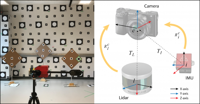
Three basic types of geometric calibration are performed: intrinsic camera calibration, intrinsic Lidar calibration and extrinsic system calibration. Intrinsic camera calibration involves modelling the lens radial distortions, lens decentering distortions, affinity/nonorthogonality of sensor and interior orientation parameters (principal point offsets and focal length). Intrinsic Lidar calibration involves modelling the systematic effects of range zero error, horizontal circle scale error and vertical circle zero index error for all the 16 laser beams in the VLP-16. System calibration, also known as ‘platform calibration’ or ‘calibration of mounting parameters’, involves measuring the rotational transformation matrix (bore-sight matrix) and a translation vector (lever arm) between the local coordinate systems of the scanner and the camera. Since the georeferencing approach also requires the INS raw measurements, the system calibration should be extended to establish the relation between the local coordinate systems of the camera and the INS as well (Figure 4, right). A software solution has been developed to enable all these calibrations to be performed simultaneously in an indoor environment (Figure 4, left). To measure the accuracy of calibration, the laser-scanner points were considered on two verification features (planes not entered in the self-calibration) from one station. Planes were fitted to these points before and after applying the intrinsic calibration parameters. The residuals from the planes before calibration were 0.008±0.006m. This was reduced to 0.005±0.003m after calibration.
Conclusion
Integration of a low-cost 3D Lidar sensor with a DSLR camera and an industrial-grade INS allows the creation of high-resolution and complete point clouds of agricultural plots and the automatic generation of a terrain model to measure soil micro-topography. The quality of the data is assured via integrated calibration that solves for all system and Lidar parameters simultaneously. The accuracy of Lidar observations can be improved by 37% via this calibration approach.
A critical challenge with this system is georeferencing the Lidar point clouds with an accuracy comparable to the georeferencing accuracy of image-based point clouds. High accuracy cannot be achieved via direct georeferencing using an industrial-grade GNSS-aided INS. Thus, the authors propose an image-aided inertial georeferencing approach that can considerably improve the results, eliminating the need for expensive, tactical-grade GNSS-inertial systems at the cost of giving the results in a local arbitrary coordinate system unless accurate GCPs can be identified for georeferencing.
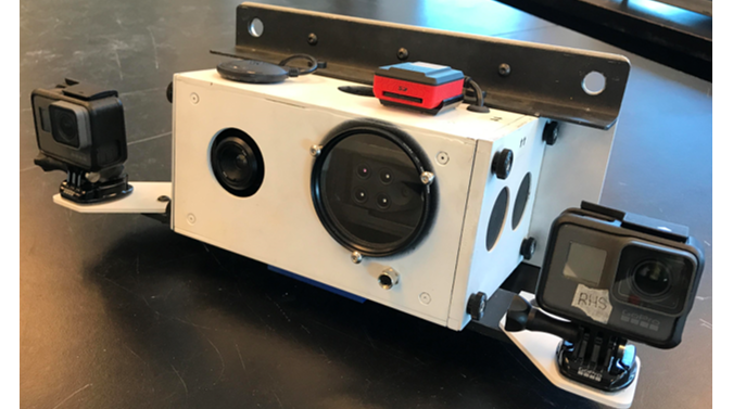
The next step will be to test the system under real conditions. Furthermore, the system will be extended with the integration of the low-cost in-house-built multi-spectral solution in Figure 5. This system is composed of a thermal infrared, a near-infrared, a red, a red-edge, a green and three RGB cameras. Using additional spectral bands, various vegetation-index 3D maps can be generated that can be used to analyse biophysical attributes of plants, e.g. Leaf Chlorophyll Index, Normalized Difference Vegetation Index, Water Stress Index, etc.

Value staying current with geomatics?
Stay on the map with our expertly curated newsletters.
We provide educational insights, industry updates, and inspiring stories to help you learn, grow, and reach your full potential in your field. Don't miss out - subscribe today and ensure you're always informed, educated, and inspired.
Choose your newsletter(s)


