Time-space Modelling with Terrestrial Lidar
Monitoring Ice Cliff Evolution of the Miage Glacier, Italy, with ILRIS-3D
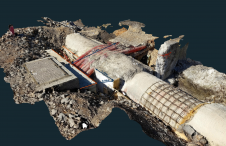
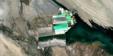
The Miage Glacier at Mont Blanc Massif, with an area totalling 11km2, is the third largest glacier in Italy. Time-space modelling of the lakebed and glacier walls carried out with terrestrial Lidar revealed that the ice cliff had retreated more than 45m between July 2003 and September 2004.
The Miage Lake area, which has been a tourist attraction and object of study for decades, has been affected by at least seventeen drainage events over the past hundred years, the most recent just last year. Observations during this last event suggest that an increased discharge of water from the lake, resulting from the opening or enlargement of a passage by the interplay of marginal crevasses or cavities, could lead to emptying of the lake. To arrive at insight into the time-space development of the area, three terrestrial laser-scanning surveys have been carried out since July 2003. For easy reference, the three models were geo-referenced in the same coordinate system.
July 2003 Survey
Terrestrial laser scanning is well suited for geophysical modelling. By collecting thousands of accurate 3D points per second over varying fields of view the surrounding terrain can be accurately modelled. The system used, Optech’s ILRIS-3D, has a working range of 3m to 1,000m in ideal conditions, depending on surface reflectivity and visibility, and has a field of view of 40° x 40° (the 360° option was not deployed). At a distance of 100m laser-beam diameter is about 30mm (perpendicular shot) and the accuracy on a flat surface is about 3-5mm. It is a hand-carried system that can be used by a single operator, which is important in remote areas such as Miage Lake. As it is impossible to cover the whole area by a single scan, partially overlapping multiple scans were acquired from various positions and subsequently merged into a single reference system. During the July 2003 survey, which represents the reference against which subsequent surveys are compared, eight scans were taken from an average distance of 300 metres from two positions located on opposite sides of the lake. The point spacing varied from 70mm to 100mm. For geo-referencing purposes, five targets were positioned within the scanned scene and their positions determined in the cartographic reference system UTM32_ED50 from three positions. The targets consisted of black square panels 50cm wide, with a white circle in the middle. By using the measured intensity of reflected signals the centres of the white circles could be automatically determined with an accuracy of a few millimetres. Static GPS phase measurements were carried out for establishing a geo-referenced baseline. Using a total station the targets were positioned with reference to the GPS baseline.
June and September 2004
The second survey was completed in June 2004 from the same positions. No targets were positioned in the scanned scene, as the June 2004 point cloud was geo-referenced by overlapping it on the unchanged areas of the July 2003 surface, represented by the moraine ridge bounding the lake to the east and west. The third and last survey was carried out on 8th September 2004, shortly after the last drainage event. As a result of the drainage most of the lake bottom was exposed and could be scanned. To ensure proper area coverage, fourteen scans were taken from three different positions. Only a small part of the western lobe of the lake could not be reached. An average point spacing of 15cm was considered satisfactory. As with the June 2004 survey, the September 2004 one was geo-referenced by overlapping the moraine ridges on the July 2003 reference surface.
Merging the Scans
Data processing following each survey was done with the commercial software package InnovMetric’s PolyWorks. The first step was removal of vegetation from the individual scans, as vegetation, subject to wind, growth and so on, does not remain coherent from one scan to another. This was done using a combination of automatic techniques and manual editing of the point cloud. To merge the individual scans into a single reference system, another module, IMAlign of the same software package, was used for choosing tie points and recognisable features present in each scan; in this case, the moraine ridges bounding the western and eastern shores of the lake. The first scan was used as a temporary reference.
A first rough alignment was carried out by manually marking three or more tie points within the overlap area of two adjacent scans. Then an automatic Iterative Closest Point (ICP) algorithm was applied to perform spatial rotation and translation without scale variation of the second scan with respect to the first (reference) scan. Six independent parameters (three rotations around the XYZ axes and three translations) were computed, providing a roto-translation matrix for each aligned scan. This procedure was applied to each individual scan, enabling the creation of a unique point cloud of the scene. To geo-reference the July 2003 survey, the centres of the targets were detected and given proper cartographic coordinates using the IMInspect module. Finally, a geo-referenced Triangulated Irregular Network (TIN) model was built using the IMMerge module; an average side of 30cm was considered satisfactory. Any data holes in the model were filled with the help of the IMEdit module.
DEM Analysis
A Digital Elevation Model (DEM) of the lake bottom was created. Analysis of the September 2004 solid model provided a detailed survey of the lake. By subtracting the DEM of the lake bottom from a flat surface representing the pre-drainage lake surface, a contour map of the lake bottom was created. The overall volume was computed as about 323,000m3, and the maximum depth as more than 23m. Details of the morphology of the lake bottom are clearly visible. As an example, the northern basin is separated from the southern one by a moraine ridge which develops along the ice foot. This can be inferred by the presence of crevasses on the bottom of the northern basin; the morphology of the southern basin looks completely different, confirming such an interpretation.

Value staying current with geomatics?
Stay on the map with our expertly curated newsletters.
We provide educational insights, industry updates, and inspiring stories to help you learn, grow, and reach your full potential in your field. Don't miss out - subscribe today and ensure you're always informed, educated, and inspired.
Choose your newsletter(s)


