Underground Mobile Mapping
Laser Scanning and Imaging of Corridors in Japan
Common mobile mapping systems heavily rely on positioning using GNSS. However, concrete, soil and other materials block GNSS signals, thus impeding their use when inspecting pipelines, subways or other underground corridors. Furthermore, such corridors are often narrow, which requires the system to be compact. Here, the author describes a platform equipped with laser scanners and a camera which has been developed in Japan for mapping a wide variety of narrow underground spaces.
Regular inspection of underground corridors is important to detect deformations and damage. The success of above-ground mobile mapping systems (MMSs) triggered us to design an MMS for use in inspecting underground corridors. The main constraints which necessitated the adaptation of conventional MMSs included:
- No receipt of GNSS signals below ground
- The system should be able to fit through manholes with a diameter as small as 60cm
- The system should be able to map corridors with a diameter as small as 80cm
- A working speed of 300 metres per hour is sufficient
- Corridors may be long, so cable-less power supply is required
- Batteries must have a long service life
Platform
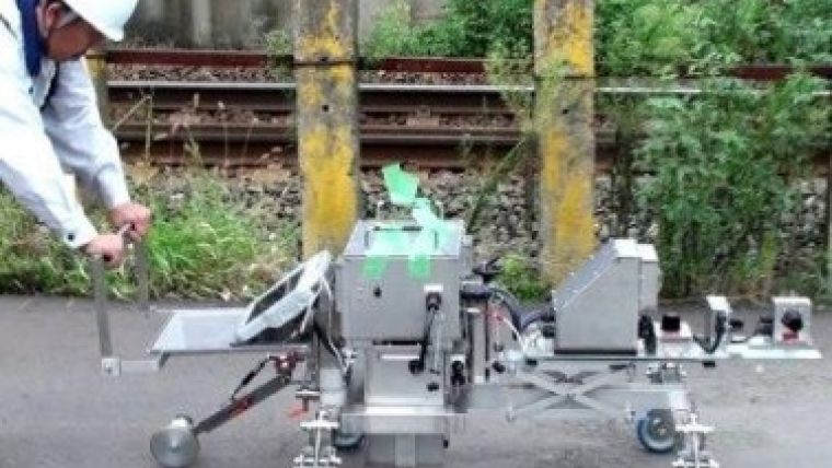
To solve the manhole issue, we have designed a modular all space mobile (ASM) system; all individual parts can fit through a 60cm-diameter manhole. After being passed through the manhole, the parts are assembled inside the corridor (Figure 1). To ensure compactness, the platform has not been equipped with an engine; instead, a human operator pushes or pulls the platform manually, or pulls it along using a rope. The platform including sensors weighs 100kg and has a length of 170cm, a width of 100cm and a height of 80cm (Figure 2).
Sensors
The main sensors (Figure 3) on board are: three laser scanners, 6 HD cameras configured to one camera system to cover a full circle, an inertial navigation unit (IMU) and odometers attached to each of the four wheels. The IMU provides the orientation and the odometers the distance. One laser scanner measures cross-sections and the other two lasers are used for determining objects for correcting the IMU orientation data. Each scanner captures a 270-degree arc across track with a frequency of 4,050 points per second. The spacing between cross-sections depends on the speed of the platform; at 300m/h the spacing between subsequent scans is 0.5cm, which is the minimum for most applications. The camera system can take both photos and videos. An on-board notebook PC collects the data and monitors the survey.
Continue reading in the online edition of GIM International.

Value staying current with geomatics?
Stay on the map with our expertly curated newsletters.
We provide educational insights, industry updates, and inspiring stories to help you learn, grow, and reach your full potential in your field. Don't miss out - subscribe today and ensure you're always informed, educated, and inspired.
Choose your newsletter(s)


