The key parameters of a modern Lidar system
How innovations in measurement technology are facilitating the work of surveyors
In the past, the effort of hardware integration and the necessary combination of different software tools was a major hurdle to gain a foothold in the field of laser scanning. This hurdle has now been removed, allowing users to focus on data acquisition and data analysis – the ‘real work’ of a surveyor. But what are the key parameters for a modern Lidar system?
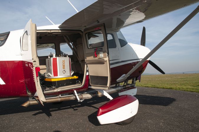
State-of-the art Lidar systems are fully integrated sensor platforms, typically comprising one or more laser scanners, digital cameras of different spectral ranges, inertial measurement units coupled with global navigation satellite system receivers, flight guidance systems and more. But a Lidar system is much more than just the hardware. Nowadays it includes means and measures for determining the optimal configuration of system parameters and flight planning tools to maximize productivity, easy-to-use software for the operator that provides direct in-flight feedback on system status and the quality of collected data and, last but not least, comprehensive data post-processing software.
Since the mid-1990s, the development of laser scanning seems to have been following the Olympic motto: ‘Citius, Altius, Fortius’ (faster, higher, stronger). In the end, however, it’s not just about a race between laser scanner manufacturers, but primarily about demanding customers and their requirements to measure ever-larger areas efficiently and cost-effectively with the aim of delivering scan data of constantly increasing resolution and accuracy.
Technological evolution
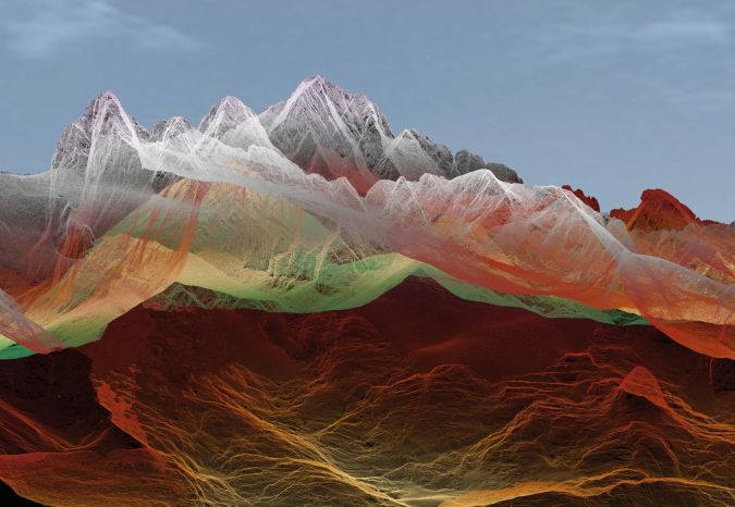
The remarkable evolution of laser technology in the last 15 to 20 years, especially in the field of fibre-amplified semiconductor lasers, has enabled an increase in achievable pulse repetition rates for time-of-flight linear Lidar sensors from about 50kHz in the past to up to 2MHz today. For example, a typical airborne laser scanning mission operating at 1,000m AGL (3,300ft) and at a flying speed of 100 knots would result in average point densities of a mere 0.5 points per square metre for the vintage 50kHz scan, and a remarkable 22.5 points/m² for the state-of-the art 2MHz scan.
Waveform analysis
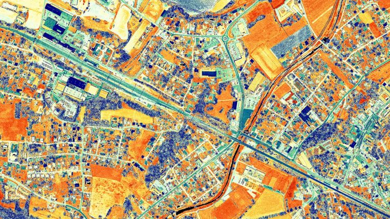
When it was introduced in 2004, the RIEGL LMS-Q560 airborne laser scanner was the first instrument with ‘echo digitization and waveform recording’ capability, a technology that is now standard and considered a ‘must have’ in any professional laser scanner sold on the market. Full waveform analysis is the key to high measurement accuracy, excellent multi-target capability and the ability to specify additional target attributes such as calibrated amplitude and reflectance, as well as pulse width. All of this required recording of massive amounts of waveform data and demanding data post-processing in the past. Nowadays, the use of waveform Lidar technology in real time significantly reduces the amount of recorded data and minimizes processing time while maintaining information content and improving measurement performance.
Resolving range ambiguities
The availability of laser sources offering high repetition rates combined with high power opened up a new problem area: the appearance of range ambiguities caused by ‘multiple-time-around’ (MTA) echoes. Due to the high pulse repetition rate, a large number of laser pulses are constantly moving along the path between the transmitter, the target and the receiver. Without additional measures, an echo cannot be definitely assigned to a laser pulse emission – the measurement range remains ambiguous. In 2011, RIEGL introduced a novel technique based on a specific modulation scheme applied to the transmit pulse train, which allows range ambiguities to be resolved without any additional information necessary. This method is indispensable today; with more than 30 laser pulses simultaneously in the air from an exemplary operating altitude of 1,800m and a pulse repetition rate of 2MHz, it resolves range ambiguities and allows gap-less data recovery over the whole measurement range.

Scanning mechanisms
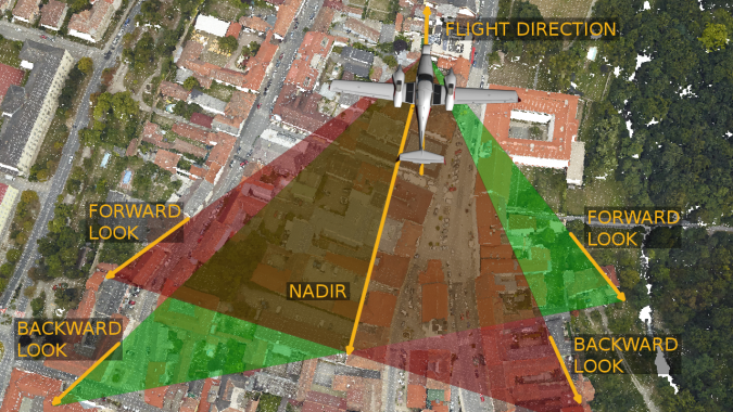
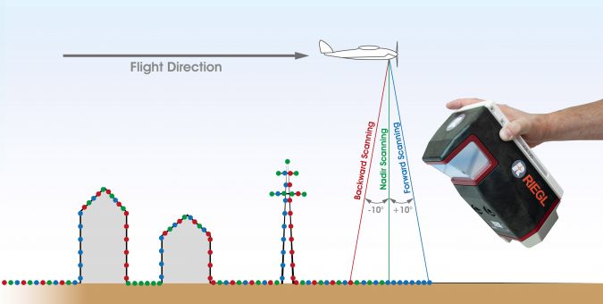
Last but not least, the scanning mechanism applied plays a central role in multiple aspects of airborne laser scanning. First and foremost, it defines the achievable point distribution and point pattern. Obtaining a regular and even point spacing over the whole swath is crucial for capturing surface details without missing objects in between individual measurements or scan lines. For that purpose, RIEGL airborne laser scanners make use of rotating polygon or prism mirror wheels. This offers a second advantage, namely the flexibility in choosing various scanner configurations optimized for their specific applications – from single-channel airborne laser scanners with a regular point and scan line spacing to more specific dual-channel systems featuring a ‘crossfire’ scan pattern minimizing shadowing effects, or even miniaturized single-channel scanners for use on unmanned aerial vehicles (UAVs or ‘drones’) with parallel scan lines and a nadir/forward/backward-looking (NFB) capability at the same time. Lastly, the continuously rotating mirror wheels enable easy control of a wide range of scan speeds to maintain consistent and regular point spacing
(regardless of air speed, altitude or pulse repetition rate), a constant wide field of view and remarkable mechanical stability, which is essential for long-lasting system calibration and geometric accuracy of measurements.
Future outlook
Based on the currently available technologies, a further increase of the maximum measurement range as well as of the measurement rate and the accuracy is only possible with difficulty. Any further increase in pulse repetition rate is already getting close to the physical limits – not only with regard to laser technology, but also to the techniques of resolving range ambiguities with a spatial laser pulse spacing already in the order of the magnitude of the object heights to be measured. With respect to a possible increase of laser power, eye safety regulations are a limiting factor. As the energy density on the ground is limited, a further increase of laser power would require higher flying altitudes, which in turn would lead to larger laser footprints, resulting in a lower spatial resolution. Moreover, adverse atmospheric effects play a significant role in the measurement error budget when scanning from high altitudes.
These challenges provide plenty of incentive for new ideas and innovative advancements. One such attempt in recent years has been the further development of Geiger mode and single photon-counting Lidar sensors for the civilian market, which were previously used for military purposes only. Following new technical approaches, the principle was to reduce the number of photons used for range finding as much as possible, enabling unprecedented flight altitude and thus optimum area yield. Multiple measurements from different angles on the same spot should yield high point density with sufficient accuracy at the same time. From the user’s practical point of view, this principle suffers from the same weaknesses as the common methods used in photogrammetry which also relies on sufficiently large image overlap: the multi-target capability and thus the penetration of vegetation to create terrain models is poor to impossible, not to mention the extensive efforts of data preparation. With regard to the detrimental influence of high altitudes on the achievable measurement accuracy, the aforementioned applies equally to all types of Lidar, whether it is Geiger, single photon-counting or linear Lidar.
Increasing area yield
A principal drive for future developments is the further increase of area yield and thus the efficiency of data acquisition while maintaining optimal point distribution on the ground. Linear Lidar, and more specifically waveform processing Lidar, will continue to be the technology of choice for providing unparalleled measurement accuracy, low ranging noise and the availability of target attributes such as height-independent calibrated reflectivity and pulse shape deviation.
UAV-Lidar mapping
Unmanned laser scanning is expected to grow significantly in the near future, with the rapid development of the UAV market driving innovation in Lidar measurement technology. Users of laser scanning systems operated on unmanned platforms expect the well-known high data quality, accuracy and similar information content of the measurements of a manned airborne laser scanning (ALS) system. Therefore, almost all known techniques for airborne laser scanners as mentioned here have been adapted or adopted to the primary requirements of unmanned laser scanning – low weight, small dimensions and high energy efficiency – at an early stage. Remarkable miniaturization has led to instruments weighing less than 2kg and operating at up to 1.8MHz pulse repetition rates, which provide survey-grade accuracies of about 1cm (1sigma) from flying altitudes of more than 135m (450ft). In turn, the newly developed manufacturing methods and the use of state-of-the-art lightweight materials are stimulating the development of new and innovative instruments for manned airborne laser scanning. All these innovations in the field of measurement technology are accompanied by immense efficiency gains through the latest developments in software algorithms, as well as simplified data evaluation and processing, which facilitate the work of surveyors.


Value staying current with geomatics?
Stay on the map with our expertly curated newsletters.
We provide educational insights, industry updates, and inspiring stories to help you learn, grow, and reach your full potential in your field. Don't miss out - subscribe today and ensure you're always informed, educated, and inspired.
Choose your newsletter(s)


