Toposcopy: Linking Photo and CAD Data
Digital Photogrammetric System for Mapping Manmade Objects
Toposcopy combines geo-referenced visualisation and close-range photogrammetry, using low-cost digital camera and CAD data. It has recently been successfully used to reconstruct a simulated traffic accident from video images. The author gives examples of system capabilities and compares it with terrestrial laser scanning.
Toposcopy produces either 3D textured or coloured 3D worlds or 2D CAD drawings of façades. At first the system was used only to accurately visualise a 3D design in a photo of the existing environment. As the system developed further it became possible to simultaneously measure and model existing buildings and other manmade objects using parametric models.
Economical Means
The means for carrying out a toposcopy survey are relatively cheap. The toposcope developed by us is independent of the availability of land-survey data and enables photos to be taken in a controlled manner. The basis of the system is an automatic level; an adapter connects the level with a digital camera. Together with the fieldwork program ‘Topo’ and a rod, the toposcope can be used as a simple tachymeter. All standard land-survey methods of determining a 3D point from angle and/or distance measurements are included. Photos are usually taken in a horizontal or upward direction When the top of a building to be modelled is not visible in the horizontal photo, then a second photo is taken in the same direction in the x/y plane, but this time with a positive vertical rotation angle. The accuracy of the data is sufficient for visualisations. However, for accurate photo-grammetric measurements we prefer to determine the position of camera and calibration points with a total station. In this case, the toposcope is still used to take photos in a controlled way and to do some supplementary angle measurements.
Visualisation Links
The main program is called ‘Scope’. Figure 1 shows the interface with loaded CAD drawing. Besides the general CAD toolbar at the top of the screen, there is also a bar with specialised tool buttons that automate procedures for making ground planes, extrusions and parametric models. The right-hand side of Figure 1 shows the calibration window, where the photo is being linked to the map. Clicking on points in the photo or on the map enters most data. Calibration varies according to the available hardware and data. When the camera point is not known, it can be calculated by clicking on three points on the map and in the photo. In such a case the angle of the viewing cone has to be estimated. When the camera point is located using a standard land-survey method, the viewing cone can be calculated instead. Orientation is determined using a 3D point known on the map and to be seen in the photo.
Photogrammetric Tools
When photos and map are linked together it is very easy to measure locations and heights by alternately clicking on points on the map and in the photo. The principles are simple and most routines work in both horizontal and upward photos.
- When the location of a point is known on the map it’s height can be determined with a single click in the photo.
- When a point lies in the vertical plane running through a line known on the map, it’s location and height can be determined with a single click in the photo.
- We can also measure like this in vertical planes that are at a certain distance from the known line.
- Only when an object is not shown on the map and it’s height is not known do we need two overlapping photos to determine both location and height.
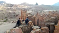
Drawing Façades
The method can be used for making accurate drawings of façades. After defining the main line of a façade on the map, all windows, doors and decorations can be measured in 3D by tracing the contours or by pointing to the diagonally opposite corners, occasionally changing the distance to the known line. This distance is positive for extruding elements and negative for sunken entrances and the like. Figure 2 shows a photo of a façade loaded into the Scope program. The traced lines are drawn on top of the photo with blue lines. Figure 3 shows the 2D CAD drawing of the entire façade. Trees and shrubs form less of a hindrance in Toposcopy than, for example, in laser scanning, because the new photogrammetric method is easier to combine with standard land-survey techniques. Where foliage screen windows it is sometimes better to accurately measure the x,y location of the windows on first-floor level with a measuring tape and to measure the height of the windows photogrammetrically only where visible. After exporting this data as a 2D CAD drawing all windows can usually be fully drawn.
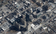
Modelling a 3D World
The Scope program has a number of specialised tools to increase the efficiency of modelling. Extrusions are set-up either by tracing an object on the map or in the photo. Many house types can be distinguished by the shape of the roof and can be constructed from five to six parameter points. During modelling one can choose how the object has to be coloured or mapped with a texture. The toposcopic database can be exported in VRML and be viewed interactively in, for example, Cortona Client. The toposcopic VRML can also be imported in professional visualisation software like 3D Studio Max and Maya and combined with 3D designs. Then it is possible also to make animations. This makes Toposcopy an efficient design and visualisation tool for use in urban planning, architecture, landscape architecture and infrastructure design.
Moving Objects
The Dutch national road department has over the years used colliding buses under controlled conditions to test many different barriers and guard rails. During these tests three video recordings were taken showing the movements of the bus and distortion of barriers and rails from above, from behind and in front. The department asked us whether it would be possible to determine with Toposcopy the space behind the barriers that must for safety reasons be kept free of obstacles. We were given access to video recordings and data described in the test reports. To answer this question, measurements had to be made of the overturn and height of the bus and dynamic distortion of the barrier rails.
Finding a Solution
This was our approach. First, describe spatially the barrier or rail, the dimensions and position of the bus just before the collision and its surroundings. Next, calculate camera position and check accuracy by drawing lines describing on top of the video frame the bus and the barrier just before the collision. Successive frames were stored with intervals of 1.2 seconds. Using the video from above, the positions of the bus as they corresponded with the stored frames were drawn on the map. Measuring could then begin. All data was referenced to the distance covered from the collision point and superimposed on the video.
Comparing Data
In many aspects, Toposcopy and terrestrial laser scanning are complementary. Laser scanning measures millions of 3D points automatically in a short time while Toposcopy measures and models a 3D object with as few points as possible by alternately clicking on points in the photo and on the map. Laser scanning is particularly interesting for making a 3D model of a complex and irregular object or group of objects. On the other hand, Toposcopy takes advantage of the regularities of many manmade objects: walls are usually upright and most buildings have some symmetry. With laser scanning, data processing to reduce the complexity of surface meshes is complex and time-consuming. In contrast, export of the toposcopic database in VRML, the 3D world, which is built mostly using parametric models, is directly fully calculated and coloured or textured automatically.

Value staying current with geomatics?
Stay on the map with our expertly curated newsletters.
We provide educational insights, industry updates, and inspiring stories to help you learn, grow, and reach your full potential in your field. Don't miss out - subscribe today and ensure you're always informed, educated, and inspired.
Choose your newsletter(s)