Water Crossing Surveys at a New Level
First Order Height Transfer With Sighting Distances Above One Kilometre
When establishing heights on large geodetic networks, the main problem surveyors encounter are wide bodies of water, such as rivers, that need to be crossed without losing accuracy. Thanks to special procedures these kinds of crossings have been successfully done in the past using levelling instruments and total stations, but seldom at a first order level when distances exceed one kilometre. Combining conventional instruments with digital camera's and image processing now brings transferral of heights with first order accuracy within reach, even with sighting distances of over one kilometre.
In June 2011, Henk ten Damme, a Dutch authority on water crossing surveys, and Ad van Vliet, an advisor of the survey department of the Dutch Directorate General of Public Works and Water Management (Rijkswaterstaat), contacted me with the request to innovate water crossing surveys. Ten Damme's idea was to mount a camera on a conventional geodetic instrument and let software take observations rather than an observer. The aim was to gather data from two instruments simultaneously that is more objective than when produced by human observation. On top of this, immediate processing was required to have the result of the survey available before leaving site.
Instrument Choice
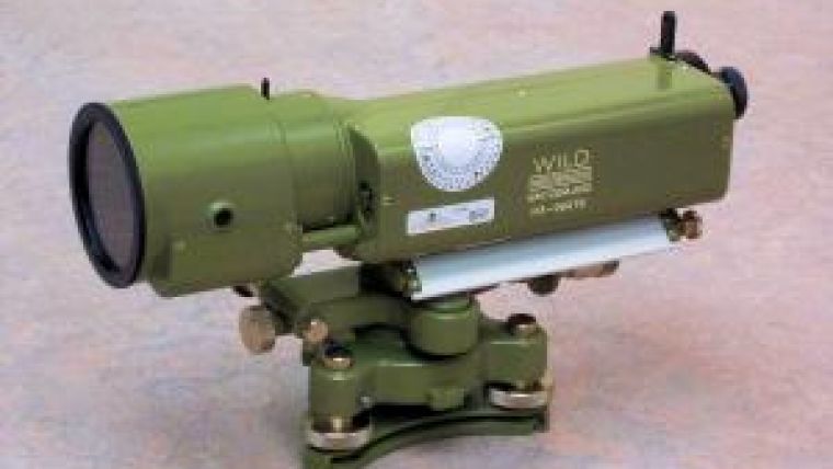
Rigth from the start it was apparent that an extremely accurate instrument would be needed. Instruments considered were a compensated Zeiss Ni002 level (accuracy of the vertical 0.05"), an uncompensated Wild T4 theodolite (0.1") and an uncompensated Wild N3 level (0.2", see figure 1). Digital levelling instruments were considered as well, but various tests in the past have shown that - even when using magnified barcode staffs - the barcode reading capabilities of these instruments at first order level is limited to less than half a kilometre.
Of the three instruments mentioned, the Wild N3 was chosen as the availability of Wild T4 theodolites and Zeiss Ni002 levels is limited and with a weight of 60 kilograms the T4 is not very practical. In addition, tests with compensated instruments have shown that compensators can be quite sensitive to temperature changes.
Camera Choice
Ten Damme proposed a USB-camera dedicated to use with microscopes. This device is meant to be mounted on the microscope's ocular and consists of a 1.3 megapixel CMOS chip and 7.2 times magnification optics. This, combined with the 42 times magnification of the Wild N3 optics, would result in an overall magnification of just over 300 times. A mount was made to attach the camera to the N3 (see figure 2), complete with adjustment screws to allow proper alignment.
Observation principle
For the observations, targets were designed consisting of two horizontal parallel bars between which the cross-hairs have to be aimed (see figure 3). The idea itself is not new, in fact it was even first described in 1594 by Thomas Harriot, and has been successfully applied since in navigational instruments, theodolite micrometers and reticules and optical tooling targets. The relative position of the cross-hairs is solved by image processing in newly developed software, written by the author.
Detecting the cross-hairs and targets is done by combining intensities from adjacent pixels of the stacked image. The horizontal line or bar of a cross-hair or target will emerge from the data as an area with constant intensity (see figure 4), the peak of which is found at sub-pixel level using a second order polynomial least squares algorithm. Tests have shown that in this way a reliable detection of 1:2,000 - 1:20,000 of the actual bar spacing can be achieved. The spacing depends on the camera and instrument magnification and is roughly 350mm for a one kilometre instrument to target distance, resulting in a 0.18mm vertical displacement detection level or better at this distance.
Software
An application was developed in Java that collects and processes images taken from the camera (see figure 4). The images are collected at a 5Hz interval and directly processed to detect the cross-hairs and target, resulting in their mutual positions. In order to overcome problems due to undulation, images are stacked (i.e. averaged over time), which is similar to the ‘integration time' used in Leica NA3003 and later digital levels. The higher the integration time, the lower the standard deviations, but the longer it takes to get a reading. The application made has a similar filter, allowing integration times up to two minutes with images being added at a 5Hz rate. The filter is designed as a Running Moving Average (RMA) thanks to which it is possible to make observations at the same speed the images are added to the stack. A mobile internet connection and a client-server set-up ensure that data is gathered simultaneously, regardless of the distance between the instruments. A web-based processing application allows the whole survey to be processed within minutes after it finished.
Connection to the benchmarks
Being disproportionate with the magnification power, the field of view is reduced to a mere 5 centimetres at 10 metres distance. Normally, reading a traditional barcode staff would require about 30 centimetres of it to be observed, resulting in a 50 metres observing distance. Undulation could then seriously affect the readings and thus a new type of barcode staff was required. An analogue INVAR barcode staff was modified by adding individual barcodes along the centimetre divisions, each representing the actual value (see figure 5). In addition, numerical values were added in a small font for visual verification. The divisions are treated as one centimetre spaced targets, which can be detected with an accuracy of about 0.005 millimetres or better at distances between 6 and 20 metres.
Field test
On 16th September 2011, a field test was conducted in IJmuiden, The Netherlands (see figure 6), in the presence of the two persons mentioned above and Jan van der Sluijs, a surveyor of the Dutch oil company NAM. A centred levelling set-up was made with two parallel 900 metres legs over water, creating a 1.8 kilometres levelling line. The height difference between the targets - which were 10 metres from each other - was determined by direct conventional levelling. Two runs were made consisting of four observation sets each over a period of two hours. All data was recorded in sets of roughly 7 minutes, resulting in a total of 12,000 observations. A third of these were rejected during the automatic post-processing, which - including the data upload - took about 10 minutes.
The closing error between the two runs was 0.69 millimetres, while the error in the observed height difference was 0.15 millimetres. The criterion for first order levelling is 2√L or 2.68mm at 1.8 kilometres distance, so in comparison this is a very satisfactory result.
The results were achieved under less than ideal conditions: A fierce wind of 17.5 knots (5Bft) blew almost head on to the instruments. It was partially cloudy, with sunny spells crossing the trajectory and during one of the runs it even rained shortly, while during another run shipping temporarily blocked the line of sight. It is expected that measurements under better conditions will improve the results.
Acknowledgements
We are grateful to both Henk ten Damme and Ad van Vliet for their suggestions and comments during the development and early tests of the system. It is thanks to their input that the accuracies achieved were made possible.

Value staying current with geomatics?
Stay on the map with our expertly curated newsletters.
We provide educational insights, industry updates, and inspiring stories to help you learn, grow, and reach your full potential in your field. Don't miss out - subscribe today and ensure you're always informed, educated, and inspired.
Choose your newsletter(s)


