Waterside Mapping in Italy
Integrating 3D Laser Scanning and Side-scan Sonar
The combination of 3D-laser scanning and side-scan sonar can be very beneficial for mapping complicated waterside areas; the two systems are complementary. High-resolution surveys were performed over a two-year period (2005 and 2006) at several locations in Italy, generating a complete and accurate digital model of areas both above and below water level, a result inimitable by any other topographical survey method.
The 3D-laser scanner used to scan the areas above water level was an Optech ILRIS while a SEA SWATHplus-H wide swath sonar system was used to collect underwater topography. Both systems generate point-clouds with attributed intensity values, although resolution and accuracy of sonar systems are much lower than those of laser scanners; the intensity values of the laser scanner are based on responses to emitted infrared waves, while those of sonar are based on backscatter strength of sound. The final product is a single 3D-model made up of bathymetry and topography to which one may add digital-camera images and side-scan mosaics for 3D photorealistic views. Main principles of laser scanning are described elsewhere in this issue; those of side-scan sonar are described in the textbox.
The Two Systems
SWATHplus is a well-established commercial tool for marine underwater mapping. It can be installed in a variety of boats and integrates motion sensing and GPS systems to correctly georeference sounding. It is well suited to shallow-water surveys, typically achieving swath widths of ten to fifteen times water depths up to 30m. Accurate positioning and motion information is required to convert the soundings into a georeferenced dataset. The Octopus F180, which was used for this, uses dual GPS antenna and motion-sensing technology. It has inertial-sensing capabilities for a fully integrated, single solution for positioning, orientation and motion. The dual-frequency (L1/L2) system when aided by RTK corrections can provide very accurate height information that can be used to provide ‘real-time tide’ information; RTK corrections of F180 data were provided by a Thales Z-max GPS. ILRIS-3D is a ground-based laser scanner that can conduct surveys from distances of 3m to over 1,500m. Recent enhancements (ILRIS-MC) allow interfacing with a GPS/IMU sensor, so bathymetric and laser surveys can be undertaken simultaneously from the same platform, saving time and increasing accuracy. This solution was not available at the time of the tests. Both systems offer advantages over traditional techniques: surveys can be completed day or night, even in heavily shadowed areas and data collection and turnaround time are both faster and cheaper.
Survey Areas
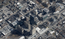
To demonstrate the abilities of the two systems as integrated, trial surveys were carried out at the River Po, Venice Grand Canal and Livorno Harbour. The River Po area was surveyed bank to bank to obtain a complete bathymetric picture of the wharfs and banks. A 7-km section was recorded over a period of six hours; river width varied between 100m and 500m, being generally 200m to 300m. The bulk of the section was surveyed in four lines. One of the two bridges in the area was laser scanned by creating four ground-station points around the bridge, two per bank. Figure 2 shows the bridge in relation to the river. The Grand Canal was surveyed bank to bank in two passes, over about three hours. In this challenging environment the F180 maintained reliable positions even when passing under bridges and close to buildings where much sky was masked. Laser scanning aimed at localisation of the poles on the wharf in front of the building, which was surveyed from the opposite bank with two scans in approximately twenty minutes; a quick business, necessitated by continual vibration and instability of the bank. Survey of the Livorno Harbour was conducted in two phases. In November 2005 the bathymetric survey produced DTM and side-scan images of the harbour. In February 2006 laser scanning resulted in analysis of the structure of the castle. Figure 4 shows part of the walls leading into the harbour, while wrecks and vessel moorings can be seen in the bathymetry.
Data Processing
The similarity of the data provided by the two systems, point-clouds and intensity values, makes easy the integration both in PolyWorks commercial software. Each laser scan has its own relative reference system, so the creation of the solid model is dependent upon the merging of all scan data using one reference system. IMAlign is a tool in PolyWorks that allows the selection of a common point to connect various scans. SWATHplus has its own software for data cleaning and DTM production. The final result is a complete point-cloud of the terrain above water level with the bathymetry below water level. Further, IMInspect enables extraction of cross-sections, so that morphology change may be studied by comparing future surveys in the same areas.
Working Experience
The two systems can be considered complementary: where neither technology can excel independently, working together the two provide a complete dataset. It is difficult to plan the exact overlapping zones for the two systems. When artificial targets are impractical it is necessary to ensure that both scans show some easily recognisable natural elements. However, the georeferencing of the laser point-cloud does speed up processing and merging of the bathymetry dataset. Merging would be further facilitated if the scanner were mounted directly on the boat and interfaced to the same positioning system used by the bathymetry system: a solution presently available.
Further Reading
- Bates, C.R., Byham, P.W., 2001; Bathymetric Sidescan Techniques
for Near Shore Surveying, The Hydrographic Journal, No. 100, April,
2001. www.hydrographicsociety.org/Articles/journal/2001/100-2.htm.
- Codevintec, 2006, Batimetria Interferometrica,Laser Scanner e Side
Scan Sonar integrati; Seminario Optech 2006,
www.codevintec.it/pdf/relazione_laserscanner_swathplus.pdf.
Side-scan Sonar
Sonar (SOund Navigation And Ranging) is a technique that uses sound propagation under water to detect underwater topography. Side-scan sonar uses the phase content of the sonar signal to measure the angle of a wave front returned from the seabed (interferometry). The wet-end hardware consists of two transducers, one facing port and the other starboard. Both are equipped with five horizontal arrays or “staves” which each produce a beam narrow in azimuth, that is, viewed from above, and wide in elevation, viewed from the side. One of the staves transmits a pulse of electrical energy at the sonar frequency, producing a narrow “shell” of sound. Where the pulse meets the seabed sound energy is scattered in all directions. When detected at the transducers, the phase difference of the signal at the four receive staves is used to calculate the angle, while the amplitude is used to record backscatter strength. The speed of sound in water is approximately 1,500m/s; range is calculated from travel time there and back. The range and angle pair enables the location of the sounding to be known relative to the sonar transducer. To geo-reference the relative location, GPS positioning is required.

Value staying current with geomatics?
Stay on the map with our expertly curated newsletters.
We provide educational insights, industry updates, and inspiring stories to help you learn, grow, and reach your full potential in your field. Don't miss out - subscribe today and ensure you're always informed, educated, and inspired.
Choose your newsletter(s)