3D Documentation of the Forth Bridge
This article was originally published in Geomatics World.
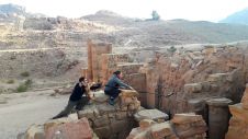
The iconic railway bridge and its companion road bridge have been scanned as part of a project to help inspire the next generation of Scottish engineers. Using a mobile mapping system engineering technology company Renishaw captured data by road and boat.
The Forth Bridge is an iconic engineering landmark located nine miles west of Edinburgh, in eastern Scotland. Opened in 1890, this cantilevered railway bridge has been nominated as Scotland’s sixth UNESCO World Heritage Site. Until 1917, when Canada’s Quebec Bridge was completed, the Forth Bridge had the longest single cantilever bridge span in the world. Together with the Forth Road Bridge and the soon-to-be-completed Queensferry Crossing (which will become the longest three-tower cable-stayed bridge in the world), the crossings will represent three centuries of Scottish engineering, innovation and design.
Renishaw was invited by the Centre for Digital Documentation and Visualisation LLP (CDDV), a collaboration between Historic Scotland and The Glasgow School of Art’s Digital Design Studio to undertake the first mobile laser scan of the two existing Forth bridges as part of a pilot survey to prove the concept and gain funding for full digital documentation of the bridges. CDDV have extensive experience of digitally documenting large and complex heritage sites around the world through their ‘Scottish Ten’ project (www.scottishten.org), which has included Mount Rushmore and Sydney Opera House. Given the limited access and complex structure of the bridges, CDDV quickly identified that mobile mapping from a vessel would be the most effective survey method in order to ensure adequate coverage of the structures, and turned to global engineering technologies company Renishaw for a solution.
Scope of Work
The Forth Bridge spans 2.5km over the Firth of Forth from Edinburgh to Fife, has a height of 100m, and a clearance of 46m above water level at high tide. It consists of two main spans of 521.3m, two side spans of 207.3m, and 15 approach spans of 51.2m.
When it opened in 1964, the 2.5km Forth Road Bridge was the longest suspension bridge of its kind outside the US, with a main span stretching 1006 m between its two towers. The bridge has a maximum height of 156m and a water clearance of 44.3m.
As part of the pilot survey, Renishaw was given one day to survey as much of the two bridges as possible. This included vessel-based scanning from the river, and road-based data capture from the bridge, using a vehicle. CDDV wanted to achieve the highest resolution and accuracy possible to capture the intricate details of the structures.
Data Acquisition
For the survey, Renishaw selected a ruggedised MX2 mobile mapping system. The MX2 can be quickly mounted on a vehicle or vessel and used to capture 3D LiDAR data of topography and structures, plus high-resolution 360° imagery. The system’s portable size and weight means it can be quickly mobilised on a vessel of opportunity within hours. This survey-grade system has a laser accuracy of ±10 mm and a maximum range of 250m. The scanning laser module (SLM) in the system can capture up to 36,000 points per second and rotates at a standard speed of 20Hz. Given the importance of acquiring data within a select, limited survey window, a single-head system was chosen as it ensures long lateral range capacity and ease of calibration.
The MX2 was accompanied by a G360 30 Mpx 360° camera to capture images triggered at 4m chainage intervals. The acquired images are synchronised at source with the raw point cloud data using the Trimble Trident Capture software. The mobile mapping system utilises a high-precision, tightly coupled global navigation satellite system (GNSS) and inertial navigation system (INS) consisting of an Applanix AP20 inertial measurement unit (IMU) to compensate for heading, pitch-and-roll of the vessel and dual GNSS antennas. Accurate 3D positioning is possible in real time using real-time kinematic (RTK) differential GNSS corrections via the onboard ultra-high frequency (UHF) radio or through post-processing using Applanix POSPac MMS software.
Alternatively, external positioning can be used if available on the vessel. In this instance, the decision was made to post-process the data as it was immediately apparent that significant multipath would be encountered from the steel structure. Also, the need to pass under the structure multiple times would introduce significant GNSS outages. In real time, the trajectory will drift from its last GNSS fix and snap back when good conditions are regained. Post-processing offers the ability to process the trajectory both forwards and backwards. When combined, the solution offers a much more accurate smoothed path throughout the outage.
For the survey, Renishaw mounted the MX2 on the front of a coastguard rescue boat and conducted an initial system check and calibration run. The bridges were then surveyed in turn at a speed of between 5 and 10 knots consisting of multiple passes alongside and beneath both bridges to ensure full coverage and maximum resolution. A ruggedised laptop was used to control the system and store the acquired survey data. As imagery was also required, the standard Trimble Trident capture software was used. However, the MX2 can also be operated with industry-standard hydrographic survey software such as QINSy and Hypack.
The survey was done at low tide to ensure optimum visibility of the structure abutments and adjacent coastline. This also had to coincide with the selected ‘best’ GNSS window. After completing the vessel-based survey, the mobile mapping system was transferred to the survey vehicle from which the road bridge and surrounding river banks were mapped. All survey data was referenced to national grid coordinates such that the multiple datasets could be overlaid on top of each other. The complete Forth Bridge and Forth Road Bridge – and the surrounding topography – were fully surveyed from both vessel and vehicle in less than one day.
Post-processing
After completion of the survey, the final smoothed best-estimate trajectories (SBET) were calculated using Applanix POSPac MMS software by combining the logged IMU inertial data with the observed GNSS positional information from the MX2 with a VRS CORS station. The resulting trajectories were then imported into the Trident Imaging Hub and used to create the 3D point cloud and to geo-reference the acquired imagery. Basic quality checks on accuracy and coverage, and data cleaning to remove erroneous points were also performed.
Due to the intricate nature of the structures and the lack of ground control, it was important to improve the matching between the multiple passes to reduce the level of noise as much as possible. To do this Renishaw used the Terramatch module of the Terrasolid software suite to optimise the dataset.
As this was a pilot survey there was no access to independent control points to verify the resulting accuracy. However, from analysis of multiple passes, the absolute accuracy of the resulting point cloud is expected to be within ±50 mm. If known ground control points were available throughout the survey area, it would have been possible to further improve the overall absolute accuracy of the data.
Lessons Learned
From undertaking the pilot survey and many other hydrographic mobile-mapping projects, there are several considerations to take into account:
Desktop planning – One of the most critical activities for any project is pre-survey planning. This includes attaining any necessary permits or access permissions, planning the best route based on coverage requirements, potential GNSS outages and naval charts, selecting ideal timing with reference to tidal charts and GNSS windows, safety considerations and development of risk assessments.
Positioning – The Applanix IMU in the MX2 is a land-based system and so does not have heave compensation, which is important when carrying out vessel surveys in choppy waters. Also typical land-based reference stations may not cover areas offshore, and RTK may be difficult to establish. It is therefore often wise to bypass the internal POS and use external navigation data – if available – on a hydrographic survey vessel as this is typically more accurate.
Environment – The setting or subject to be surveyed can have a big impact on how the data is collected to provide optimum results. When surveying close to a large structure like the Forth Bridge you will encounter GNSS outages and multipath that can seriously jeopardise the accuracy of the resulting data. It is therefore important to plan your survey route to maximise open sky and observe good static conditions before and after entering any areas of poor GNSS. If poor coverage is expected or observed it may be necessary to consider control points at regular intervals to improve or maintain overall accuracy. This also offers a quality-assurance method comparing mobile with traditional survey.
Access – Often for hydrographic applications it is neither possible nor safe to survey in close proximity to the subject, meaning laser range is important. Correct selection of equipment should be considered. The single-head MX2 system offers a longer lateral range as the scanning head is mounted perpendicular to the vessel. The dual-head system offers higher resolution but as the lasers are mounted at 45 degrees the lateral range is reduced. The colour, condition and material of the survey subject may also affect the useable range of the scanner and dictate how close the scanner will need to be to achieve good results. Finally, the further away you are, the lower the resolution and accuracy of the point cloud, and the less effective the camera will be.
Survey platform – One of the benefits of the MX2 system is the speed of mobilisation on a vessel of opportunity, however, there are a number of factors to consider. The MX2 requires an 11-36V DC power supply (typical car battery) and a second GPS antenna to be positioned ideally a minimum of 2m in front of the scanner to provide improved GAMS (GPS Azimuth Measurement System) heading orientation. Greater antenna separation will improve accuracy but may not be practical. If connecting just the laser to an existing system the dual antennas are not required. Finally, it is critical to ensure that the MX2 is mounted such that the scanning laser head and GNSS antennas have a clear, unobstructed field of view.
Multibeam – As all of the Renishaw mobile mapping systems can be operated using industry-standard hydrographic survey software, it is possible to use them in conjunction with multi-beam echo sounders (MBES) to simultaneously acquire data both above and below the waterline. If the intention is also to acquire MBES bathymetric data it is preferential to use common navigation information for both sensors. Also if MBES is being captured simultaneously the acquisition method and route may need to be reconsidered in line with the specification and resolution of the MBES survey.
Conclusion
Following the successful pilot survey, CDDV has been awarded £300k of funding from the Scottish government to digitally map and scan the three major bridges across the Firth of Forth in full detail. The digital content from the project will be used to provide animations, fly-throughs and educational materials that will be shared across primary schools and used to help inspire the next generation of Scottish engineers. The full project will now commence in 2015, carried out by CDDV with the help of specialist teams where necessary.
This article was published in Geomatics World May/June 2015

Value staying current with geomatics?
Stay on the map with our expertly curated newsletters.
We provide educational insights, industry updates, and inspiring stories to help you learn, grow, and reach your full potential in your field. Don't miss out - subscribe today and ensure you're always informed, educated, and inspired.
Choose your newsletter(s)