How UAV Lidar improves landmine clearance planning
A project in Angola
British mine-clearance charity The HALO Trust partnered with Routescene to undertake a UAV Lidar project in Cuito Cuanavale, in the Angolan province of Cuando Cubango. This case study demonstrates the benefits of UAV Lidar to detect and map minefield features as the basis for informing clearance planning. The results can make clearance efforts safer and can expedite clearance through a targeted approach.
Land mines indiscriminately maim and kill countless animals and as many as 5,000 people annually, rendering habitats inaccessible and unusable, and destroying lives and livelihoods. At least 60 states and territories around the world are contaminated by landmines, whether due to the legacy of the past or as the consequence of recent or ongoing conflicts, such as in Ukraine and other areas. Clearance is a painstakingly slow and expensive process and there is a clear need to accelerate landmine clearance across the world.
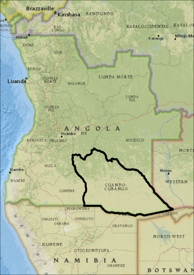
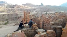
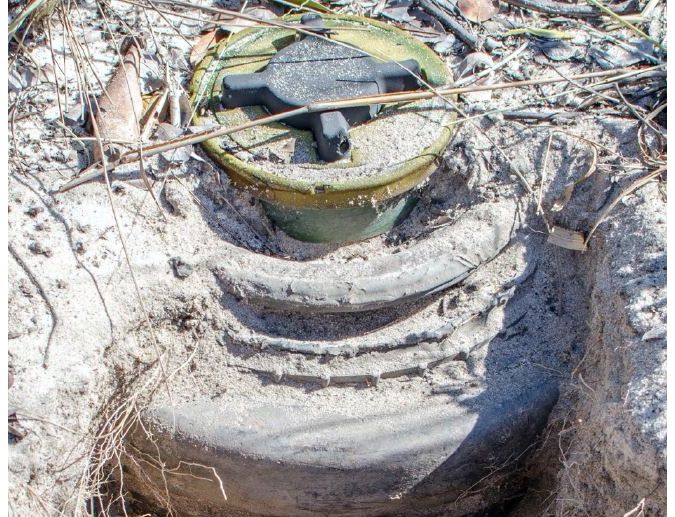
In Angola, the landmines are a remnant of the civil war that lasted from 1975 until 2002. The province of Cuando Cubango (Figure 1) saw some of the heaviest fighting, and the Battle of Cuito Cuanavale was the largest conflict of the war. Throughout the conflict, there was extensive mine laying by both sides, resulting in multiple minefield sites. Many of them are 20-30km long, including mixed-threat mine belts of anti-vehicle (AV) and anti-personnel (AP) mines which continue to pose a deadly threat to the local community (Figure 2).
To support the clearance operations that began in Cuito Cuanavale in 2005, The HALO Trust trialled the use of remote sensing using uncrewed aerial vehicles (UAVs or ‘drones’) including thermal infrared (TIR) and RGB cameras to identify unexploded ordnance (UXO). However, many indicators of conflict which would suggest the presence of AV and AP mines – such as trenches, bunkers or craters – are now overgrown with vegetation and are no longer visible from the ground or the air using UAV-mounted RGB or TIR sensors. Therefore, another method of detection was needed. UAV Lidar was identified as a possible solution thanks to its ability to penetrate vegetation and enable the survey team to map an area and predict where a mine line may be located.
Initial validation in Scotland
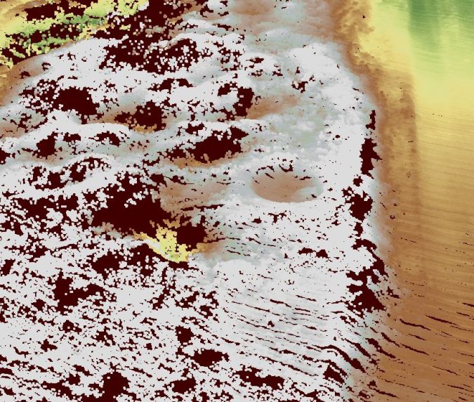
Routescene, a manufacturer of UAV Lidar systems and software, and The HALO Trust, both headquartered in Scotland, first performed a test locally in 2020 to confirm that UAV Lidar could effectively map battlefield remains which would be identifiable in the post-processing software. A suitably vegetated site was found and a replica crater was dug to represent the conditions found in Angola. The simulated crater was easily identified in the resulting digital terrain model (DTM) (Figure 3). This validated that UAV Lidar would be capable of locating and mapping battlefield remains in Angola.
The Angolan project
The aim of the survey project was to detect battlefield features including main trenches, communication trenches, foxholes (one-man defensive positions), shell scrapes (shallow excavations allowing soldiers to shield from shell bursts and small arms fire) and craters from detonations. Three sites with known or suspected battlefield features were chosen for the Angolan project:
- Site A: an abandoned military base outside of Longa village, 100km northwest of Cuito Cuanavale
- Site B: an extensive defensive mine line with an associated trench, 9km east of Cuito Cuanavale
- Site C: an abandoned military base, 25km southeast of Cuito Cuanavale.
The terrain across the three sites was similar in terms of elevation, all being relatively flat. However, the degree of vegetation coverage varied considerably. Sites A and C had dense tree coverage, whereas Site B had light tree and shrub coverage.
Equipment and software
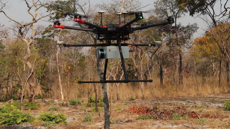
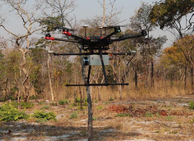
A demonstration UAV Lidar system was constructed for this project comprising a 16-channel Lidar sensor capable of collecting approximately 600,000 points per second, a GNSS/INS sensor, and data storage to capture 12 hours of data. The system was designed to be resistant to in-flight vibrations and handling by users, and did not require a mobile or internet connection to operate, thus providing operational autonomy and data security. GNSS data was collected for the post-processing of the trajectory to ensure the data was as accurate as possible. The UAV Lidar system was mounted onto a hexacopter capable of lifting a 5kg payload for approximately 15 minutes (Figure 4).
Data collection challenges
At Sites A and B, Lidar data was collected at 40m above ground level (AGL), with one day of collection being sufficient for each site. At Site C, data was collected over three days and at 50m AGL. This higher altitude was due to the size of the area and time limitations. Moreover, Sites A and B were surveyed during the dry season (August 2021) when vegetation cover was at its lowest. Site C was surveyed during the rainy season (April 2022) when vegetation cover was at its highest.
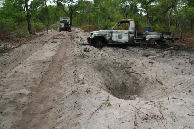
Practical challenges included a shortage of suitable drone take-off and landing sites and difficulties in siting the base station. At Sites A and B, breach lanes and cleared land were available near the areas of interest. In contrast, Site C was limited by the surrounding uncleared terrain which contained mines and potentially endangered the survey team. Therefore, the cleared narrow sandy roads were used both as the drone take-off and landing sites and to site the base station. This meant that the equipment sometimes needed to be moved to let vehicles past (Figure 5).
Results
The raw Lidar datasets were processed using Routescene’s LidarViewer Pro software to create and export DTMs from each of the sites for analysis in ArcGIS Pro. In areas where there were large gaps in the mine lines or a sharp change in direction, the UAV Lidar data was analysed to identify the locations of craters from mine detonations, often caused by animal accidents and wildfires, to indicate the location of the mine line. The analysis of DTMs created from the Lidar data showed positive results for the use of UAV Lidar for battlefield feature detection across all three locations.
Site A: Satellite imagery at Site A showed little evidence of the historical military base. An access path was visible, but it was not possible to identify other features. Due to a lack of safe access, only a partial UAV Lidar survey was completed. Nevertheless, when the UAV Lidar data was overlaid onto satellite imagery, multiple features became apparent. The predominant feature was the defensive main trench around the former base, with a communications trench branching off the northwestern internal side of the main trench (Figure 6). In total, 40m of communication trenches and 496m of main trench were identified.
A further 24 feature points were identified:10 foxholes follow the inside of the main trench dug as defensive positions; nine crater-like features clustered inside the base, with two further north near the communications trench (these are suspected shell scrapes); and a line of six crater-like features outside the main trench (unlikely to be AV mines as none were found at this location, so these may be shell scrapes).
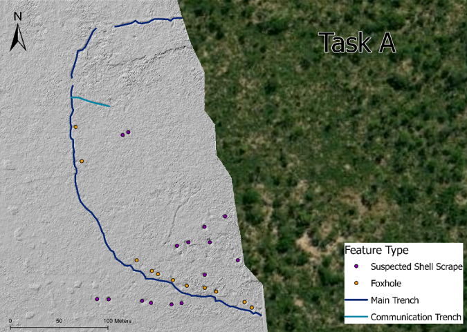
The feature types were confirmed with a ground mission where accessibility and vegetation coverage allowed. The average depth and width of the foxholes (0.58m and 2.36m respectively) and the suspected shell scrapes (0.77m and 2.38m respectively) were similar, suggesting these are the same type of feature. However, the suspected shell scrapes were identified as a separate feature due to not being in the typical location and pattern of foxholes.
Site B: Due to thick vegetation and lack of safe access at this site, it was difficult to see what remained of the trench system during field visits. The lighter vegetation coverage at Site B meant that there was slight evidence of the main trench remains in the satellite imagery. However, other features were not visible. Analysis of the UAV Lidar data identified multiple features including a larger extent of the main trench, communication trenches, foxholes and suspected craters (Figure 7).
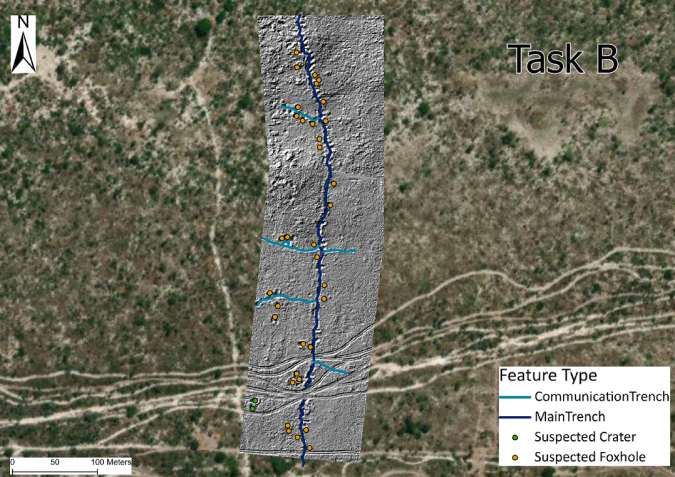
In total, 500m of main trench and 281m of communication trenches were identified, alongside 34 foxholes and two suspected craters (possibly from exploded ordnance but unlikely to be from AV mines). The suspected craters were in an uncleared area so it was not possible to access them to confirm their exact nature. The suspected craters averaged 5.85m in width and 0.65m in depth, and the foxholes averaged 0.67m in depth and 2.54m in width. Whilst the majority of the tracks were visible in the satellite imagery, the UAV Lidar data revealed additional historical tracks. This information was used to identify locations of possible safe access roads to the site.
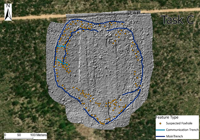
Site C: This site showed evidence of AP mine laying within the previous military base and was suspected to have at least a single trench and multiple foxholes. However, due to the dense vegetation, it was not possible to identify the locations of the suspected battlefield features from satellite imagery nor from the ground.
The UAV Lidar data showed evidence of two trench systems surrounding the former base as well as communication trenches (Figure 8). The data evidenced 157 crater-like features which follow both trench lines, believed to be foxholes due to their regular spacing in close proximity to the trench lines. The data also highlighted gaps in the trench systems which could be explained by the infill of soil levelling out the ground within the trench over time, or rainwater lying in the trench preventing the Lidar pulses from reaching the bottom.
Although the trench data was incomplete, the continuation of foxholes between the two extents of the inner trench suggests that the trench once continued to create a circular inner trench system. Overall, 1,429m of main trench (828m on the outer trench and 601m of inner trench), 73m of communication trench and 157 foxholes were identified at this site. The foxholes averaged 0.80m in depth and 2.81m in width.
Conclusion
Remote sensing is complementary to conventional minefield survey techniques as it provides information that is not obtainable by any other means. Within The HALO Trust’s mine clearance operations in Angola, the UAV Lidar data outputs – combined with contextual knowledge on the ground – provided valuable information to supplement conventional survey operations. At all the sites surveyed, the UAV Lidar data provided evidence of trenches, craters and foxholes – features that were either not detectable or only partially visible in satellite imagery, RGB/TIR imagery or from the ground. Therefore, this project demonstrates that UAV Lidar can be used successfully to detect battlefield features that may be indicators of minelaying, particularly when those battlefield features are hidden by vegetation. That evidence can then be used to create targeted clearance plans, making clearance efforts faster and safer.
Acknowledgements
The HALO Trust would like to thank the anonymous private donor for their extremely generous support for the UAV trials in Angola and their commitment to innovation in mine action; this project would not have been possible without their help. Thanks also to go to Routescene for providing the UAV Lidar system, software training and ongoing support since 2020. Last but not least, thanks to Claire Lovelace and Siân McGee from The HALO Trust Angola programme for their ongoing support, both in the field and during data analysis.
Further reading
Landmine Monitor 2022, http://www.the-monitor.org/en-gb/reports/2022/landmine-monitor-2022/major-findings.aspx
- Pearce, Control, politics and identity in the Angolan Civil War, African Affairs, Vol. 111, No. 444 (2012).
- Mills and D. Williams, 7 Battles that Shaped South Africa, 2010, Tafelberg
- Fardoulis, X. Depreytere and J. Guthrie, Proof: How TIR imaging can locate buried cluster munitions in the Iraqi Desert, The Journal of Conventional Weapons Destruction, Vol. 25, No. 3 (2022).
- Fardoulis, X. Depreytere, P. Gallien, K. Djouri, B. Abourahmane and E. Sauvage, Proof: How small drones can find buried landmines in the desert using airborne IR thermography, The Journal of Conventional Weapons Destruction, Vol. 24, No. 2 (2020).
- Shaughnessy, Some thoughts about Private Harold L. Green of the Scout Platoon, First Battalion, the Royal Hamilton Light Infantry, Canadian Military History, Vol 10. No. 1 (2001).

Value staying current with geomatics?
Stay on the map with our expertly curated newsletters.
We provide educational insights, industry updates, and inspiring stories to help you learn, grow, and reach your full potential in your field. Don't miss out - subscribe today and ensure you're always informed, educated, and inspired.
Choose your newsletter(s)