An Indoor Mapping Test for the ZEB1
This article was originally published in Geomatics World.
The ZEB1 handheld laser scanner has been in production for over a year and in use the novel spring mounted system still gets the odd strange glance. The system consists of a 2D laser scanner rigidly fixed to a MEMS IMU. Both sit on a spring which keeps them in constant and random motion. So, is this the ideal tool for interior mapping and many BIM applications?
In this handheld system data is captured at walking speed, as the user moves through the desired environment. On finishing capture, data is transferred to the Geoslam servers where an innovative simultaneous localization and mapping (SLAM) algorithm combines the raw data to produce a full 3D point cloud that can be downloaded and ready for users to integrate into existing workflows. This novel approach to processing removes the need for long hours spent at the computer trying to register independent scans together. Rather, the data is processed automatically without need for user intervention. Users are advised not to collect more than 20 minutes worth of data in one mission but, at average walking speed, a user can collect up to 1km worth of data in that short period.
At first sight the interesting design of the ZEB1 may appear gimmicky, but it is in fact the product of many years of research carried out by the Australian Research body CSIRO, which has culminated in the production of a survey-ready tool. The reader is directed to Bosse et al. 2012 (https://dl.dropboxusercontent.com/u/7114463/publications/bosse_tro2012.pdf ) for an in-depth explanation of the hardware and software research that has been undertaken.
Hard-to-survey environments
ZEB1 now has multiple users around the world collecting data of differing environments including underground mining, caving, building interiors, building exteriors and forestry. The device is often used in hard-to-survey environments where other equipment is either too bulky or too time consuming to be cost effective. All this means that the ZEB1 is being tested to its limits on a daily basis and the Geoslam team are learning more and more about efficient and effective operation of the system; determining which environments are suitable for such a tool and which are not. This article offers some insight into the capabilities of the system for interior mapping and building information management.
Preliminary testing
The most frequently asked question from prospective users is: ‘How accurate is the system?’ In truth, this is dependent on the operating environment. The ZEB1 uses the shape of the environment around it to calculate its current position. So, if the environment is poor then the results will also be poor. The best kinds of environment for the ZEB1 are locations such as building interiors or underground tunnels where there are lots of features all facing in different directions. Problem environments tend to be open spaces or long featureless corridors where the lack of detail makes it difficult for the ZEB1 algorithm to determine its position.
Some basic laboratory testing has been undertaken to see how accurate the system can be. Tests were undertaken at the 3DLM Research lab in the UK. Three spheres were positioned in the workshop and the area was scanned using the ZEB1 and with a Riegl VZ400 scanner.
The 2D scanner atop the ZEB1 has a measurement accuracy of ±30mm so instead of comparing individual points, the data is modelled and the results are compared against the terrestrial laser scanning (TLS) data. The three spheres present in the scan were modelled and the calculated centre position was compared. The modelling of the spheres was undertaken using both a fixed sphere size and a free sphere size to help determine how well the sphere was modelled.
The largest error is 6mm, the accuracy of the 2D laser scanner is ±30mm. However, as stated before, this is the optimum environment for using the ZEB1 due to all the features in the environment, so further tests have been undertaken in a building that is more representative of typical usage.
BIM
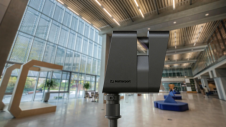
The main benefit of ZEB1 is its rapid data capture time. There is no need to spend time setting up equipment and data can be collected at walking pace as the user moves through the environment. These qualities make it ideal for repetitive measurements of indoor locations, for applications such as maps for personal navigation, security, project management and building information management. A trial was undertaken at the Nottingham Geospatial Institute (NGI) to provide validation of the ability of the ZEB1 to perform internal building surveys.
The NGI is an office environment, constructed from a variety of manmade and natural materials. The layout is typical of office spaces with a mixture of large open areas such as an open-plan office and an entrance atrium as well as smaller environments such as emergency exit stairwells and personal offices. The building reflects a typical operating environment for the ZEB1.
Data was collected over all three floors of the NGI in around 22 minutes. To determine the absolute accuracy of the data it was analysed against a ground truth TLS scan provided by a FARO Focus 3D. The FARO data was registered together using spheres positioned in the data and accomplished using the FARO Scene software with a standard deviation of 0.002m. As the ZEB1 produces data in a local coordinate system the data was transformed onto the FARO data using a variation of the Iterative Closest Point (ICP) algorithm, with a standard deviation of 0.025m. This value reflects the accuracy of the 2D scanner used in the head of the ZEB1.
Once the data was in the same coordinate system it was analysed for noise to determine how well planes can be fitted to the data, for the creation of building models. Areas of 1m2 throughout the scan were analysed looking at different building materials to determine if this had any influence. The areas analysed were hard floor, plastered walls, wooden doors and carpeted floor. A plane was fitted on the different areas and the standard deviation to the plane was measured.
Accuracy
The ZEB1 scans were compared against the FARO data using the open source software, Cloud Compare. Each floor of the building was compared independently to keep the datasets to a manageable size for the software. The ZEB1 data has fewer shadow areas within its dataset due to the scanner’s manoeuvrability during operation. It is possible to navigate around objects to achieve higher data coverage in less time. On the other hand, TLS must be performed in stationary locations and as such there are always shadowed areas which can only be reduced with careful planning and additional setups. This difference between coverage is accounted-for by setting a maximum limit to the distance that a ZEB1 point can be from the FARO data. In this trial the limit was set to 0.3m as it is not expected that any ZEB1 data would be that far from its ‘true’ location. It can be seen that the majority of points lie within 0.0325m of their true location. The areas shown in red are where the FARO does not provide any reference data and emphasises the coverage achieved with the ZEB1 unit.
Comparison against design plan
The data was also assessed against a design plan of the building held by the University Estates office. This was undertaken to try and establish the ability of the ZEB1 to efficiently report the as-built design for building management purposes. The floors and ceilings of the ZEB1 data were removed to see more easily the building dimensions for comparison, also all layers, apart from those about visible aspects of the design plan, were turned off.
When comparing the data against the design plans it could be seen that 58% of the doorways on the plan were more than 50 cms from their true location as detected by the ZEB1. Of those that were wrong 54% were widely different, e.g. the entrance to rooms was on a different wall. Some of these areas were then inspected using manual measurements of the location to understand the usability of the ZEB1 for the creation of as-built plans. The maximum error of the ZEB1 data from the manual measurements of the area is 0.028m, which is consistent with the other areas tested within the whole dataset and is also consistent with the accuracy of the 2D scanner on the ZEB1.
In conclusion
From testing, the conclusion can be drawn that the relative accuracy of the ZEB1 is in the region of ±3cm. An advantage of the ZEB1 is its manoeuvrability and high speed data capture that will aid the user to efficiently update building plans without the need to set up any equipment. An additional benefit is that there is minimum disturbance either during construction or whilst the building is in operation. The accuracy of the data produced is suitable for building management and maintenance. With the ability to quickly scan the area, the system could be used on a more regular basis for tasks such as building occupancy vs. capacity for large organisations along with the monitoring of office equipment.
This article was published in Geomatics World January/February 2015

Value staying current with geomatics?
Stay on the map with our expertly curated newsletters.
We provide educational insights, industry updates, and inspiring stories to help you learn, grow, and reach your full potential in your field. Don't miss out - subscribe today and ensure you're always informed, educated, and inspired.
Choose your newsletter(s)