Peak performance in mobile mapping
Strategic imperatives to achieving centimetre-level accuracy
It can still be difficult to achieve centimetre-level accuracy in mobile mapping, especially in GNSS-denied or challenging areas such as in deep urban canyons, under foliage or through tunnels. However, with the right combination of sensors and technologies, it is possible nowadays. The most accurate and capable mobile mapping systems incorporate carefully integrated sensors that are precisely calibrated and use the most advanced sensor fusion algorithms and technologies such as Lidar simultaneous localization and mapping (SLAM) to georeference their data.
High-accuracy mobile mapping has become a foundational tool, whether application specific – such as transportation infrastructure – or in the context of the broader smart city, digital twin evolution. Yet for true continuing value, the resulting data must achieve centimetre-level accuracy across an ever-changing and challenging landscape.
Precision calibration
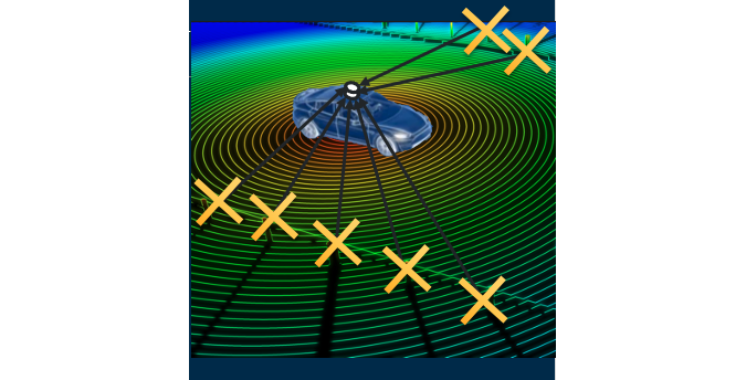
Today’s high-end mobile mapping platforms integrate multiple positioning technologies such as inertial measurement units (IMUs), GNSS, Lidar, cameras and other sensor systems to achieve centimetre-level accuracy. While each of these sensors have their own limitations (e.g. line of sight in the case of GNSS and Lidar, inertial drift in the case of IMU), when skilfully combined these limitations can be overcome to produce a ‘fused’ high-accuracy solution.
To achieve consistent centimetre-level accuracy in all environments requires high-precision system calibration. This involves the precise determination of misalignment angles (boresight angles) and positional offsets (lever arms) between the sensors placed around the survey vehicle. As an example, for best satellite visibility, Lidar sensors might be mounted on the corners of the roof, a camera at the centre of the roof and the GNSS antennas elsewhere to enable best satellite visibility. Even the slightest inaccuracy of calibration between the sensors can create errors that will limit – and perhaps even eliminate – the ability to achieve centimetre-level accuracy.
Boresight benefits
While many of the calibrations between co-located sensors can be done in the factory during manufacture, most of the parameters need to be calibrated or refined in-situ. This is done using the manufacturer’s calibration software and by collecting data following a specific procedure. In general, the lever arms and misalignments between the IMU, the GNSS antennas and the vehicle are calibrated by making them observable through dynamics (e.g. turns), while the lever arms and boresight angles of the Lidar sensors and cameras are computed using Lidar SLAM and photogrammetry.
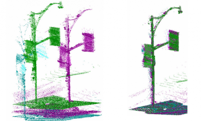
One of the most accurate means of using Lidar SLAM to calibrate Lidar lever arms and boresight angles is to use a global iterative least squares adjustment operating on voxels. i.e. 3D pixels. Voxels are created from the Lidar data and are then matched from subsequent scans of overlapping regions. The iterative least squares adjustment solves for the constant Lidar boresight angles and lever arms offsets that are necessary for generating a very high-accuracy point cloud.
On the right trajectory
Once the calibration is done, trajectory optimization is the second strategy to achieve the highest level of accuracy, reliability and efficiency. The trajectory – i.e. the position and orientation of the mapping sensors measured as the vehicle moves – is used to geocode each pixel and point recorded by the sensors. Trajectory optimization involves ensuring errors are kept at a minimum through proper planning and data collection to ensure that the desired accuracy of the digital map product can be achieved.
Planning includes making decisions such as which aiding sensors to use, which GNSS augmentation methods to use, and the necessary collection geometry (e.g. single pass, multi-pass). This is particularly important in the most challenging GNSS-denied environments such as urban canyons or tunnels.
While the trajectory of a mobile mapping platform is primarily computed using GNSS and inertial sensors, additional aiding sensors such as Lidar SLAM and wheel-mounted odometry (i.e. distance measurement indicators or ‘DMIs’) can be deployed to remove or constrain drift in poor GNSS environments.

Post-processing for ultimate accuracy
Map creation is normally done in post-mission processing, either on a desktop computer or in the cloud. The aim is to produce the highest accuracy by taking advantage of scalable computational power, internet-based correction services and the ability to process data temporally, in the forward and reverse direction, and globally in the spatial domain. Accurate georeferencing is reliant upon the most accurate trajectory possible.
In post-processing, Lidar SLAM for trajectory adjustment can take advantage of using all overlapping points collected for the entire project area, regardless of when they were collected temporally. This makes errors in the trajectory highly observable for the most accurate correction. For example, it is possible to simultaneously use points that were collected in opposite directions or from inside a tunnel without GNSS, and overlapping points collected outside with GNSS.
In real time for quick answers
When time is more important than accuracy, mobile mapping systems can also produce map products in real time. While this means they cannot take advantage of forward/reverse processing and global trajectory adjustments, SLAM techniques can still be used to correct or constrain drift in the absence of GNSS.
Map-based localization (MBL) is a method of using Lidar or image-based SLAM to provide constant and precise positioning, even without GNSS. This involves using an a-priori collected basemap loaded into the vehicle, and deriving the absolute position and orientation of the vehicle by matching features observed in the Lidar or imagery on the map as it moves. This can be done anywhere (including indoors) and from any type of vehicle.
The same SLAM technology used for MBL can also be used to reduce position error drift even if an existing basemap is not available. This technique is referred to as visual odometry (VO). In this case, overlapping images or Lidar scans are matched and used to estimate and correct for drifting position error when GNSS is not present. VO is a useful alternative for vehicles where traditional wheel-based DMIs are not practical (e.g. tracked vehicles, off-road vehicles, human-portable systems).
Lidar-based MBL and VO will tend to be more accurate than image-based approaches. This is because cameras rely on lighting conditions and can be affected by the challenges associated with matching points in homogeneous scenes, as well as with fast-moving vehicles which can cause image smear.
Parked with precision
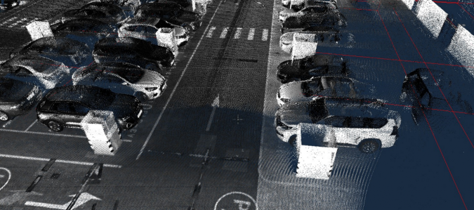
In China, location service and smart mobility provider NavInfo used mobile mapping as the foundation for an automated valet parking (AVP) garage project. AVP is a sensor-based solution that automatically drives a car to a parking spot and then returns to a designated pickup point when authorized. To make sure cars are parked with precision, the foundation map needed to be accurate to within ten centimetres for its 1,000 parking spaces.
NavInfo used a GNSS-inertial mobile mapping platform along with Lidar as an additional aiding sensor, with a post-processed georeferencing Lidar point cloud and trajectory adjustment software. Using a combination of survey-grade GNSS/IMU sensors, DMI and Lidar-aiding SLAM technology, it was possible to achieve the required 10cm accuracy for the AVP basemap. The accurate and robust final trajectory solution is used to georeference all sensors onboard the vehicle with extreme accuracy.
Parameters and possibilities
In summary, there are multiple ways of achieving centimetre-level accuracy in mobile mapping, whether using VO, MBL, SLAM and/or post-processing trajectory adjustment, thus making the accuracy goal achievable.

Value staying current with geomatics?
Stay on the map with our expertly curated newsletters.
We provide educational insights, industry updates, and inspiring stories to help you learn, grow, and reach your full potential in your field. Don't miss out - subscribe today and ensure you're always informed, educated, and inspired.
Choose your newsletter(s)