Deformation Analysis of a Test Dike
Dikes play a vital role in preventing floods around the world. Typically, dikes are made of clay or marl, but these soil materials are becoming scarce in some regions. In Germany, an experimental test dike was constructed to evaluate the suitability of three other materials. Terrestrial laser scanning (TLS) and photogrammetry from an unmanned aerial system (UAS) were used to monitor the deformations of the dike. This provided valuable insights, not only into the dike deformations but also into the suitability of UAS photogrammetry for deformation monitoring.
By Matthias Naumann and Ralf Bill, University of Rostock, Germany
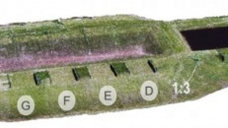
The accuracy of deformation monitoring is determined by both the spatial and the temporal resolution of the observations. Laser scanning is a suitable method to achieve a high spatial resolution, but also comes at a high cost. Hence, it is uneconomical to apply laser scanning with a high repeat frequency. Now that UAS-based photogrammetry is becoming a mature technology, a new and affordable tool for deformation analysis is available. To test the accuracy and hence suitability of UAS photogrammetry for dike deformation monitoring, five surveys were performed over a test dike and the results were compared against a terrestrial laser scan survey conducted for reference purposes. The image shows a photorealistic textured DSM of the Rostock test dike.
Test Dike
Dredging is necessary in many harbours and waterways around the world to maintain sufficient depth for shipping, and the dredged material is pumped onshore into basins where it is prepared for re-use. Until now, it has been difficult to re-use the fine-grain fractions in that material. To evaluate whether those fractions could be suitable for building dikes, a number of test dikes have been constructed within the international DredgDike project. One such large-scale experimental test dike is located in Rostock-Markgrafenheide, Germany. The dike has been made entirely from materials dredged from the nearby harbour and waterways.
There are two parallel dikes approximately 130m long and 3.3m high. The dikes are used to form a number of polders that can be filled with water for testing purposes. Along the dike, eight different regions are defined. These regions vary in the type of dredged material, slope and the applied geosynthetics. One side of the dike is used to test seepage and moisture, while the other side is used for overflow experiments.
Two Multirotor Platforms
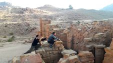
There are many micro UASs available on the market nowadays, and they often excel in either payload capacity or flight duration. The decision was taken to fly two different systems for the deformation tests in order to compare and evaluate the systems. The first three surveys were flown with the MD4-1000, a quadrocopter from Microdrones with the Olympus PEN e-P2 camera using a fixed focal length of 17mm. The final two flights were conducted using the AscTec Falcon 8, an octocopter from Ascending Technologies GmbH with the Sony NEX-5 camera and a focal length of 16mm. Both UASs are standard models without further additions and integrate a GNSS, an inertial measurement unit and an active stabilising camera mount. For oblique-looking photos the Falcon 8 is predestined, which is suitable for steep areas or retaining walls. Due to its much longer flight time capability, the MD4-1000 is suitable for larger or longer dike sections.
Continue reading in the online edition of GIM International (login or registration may be required)

Value staying current with geomatics?
Stay on the map with our expertly curated newsletters.
We provide educational insights, industry updates, and inspiring stories to help you learn, grow, and reach your full potential in your field. Don't miss out - subscribe today and ensure you're always informed, educated, and inspired.
Choose your newsletter(s)